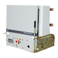
Power Break
®
Circuit Breakers
Table of Contents
ii
Chapter 1. Receiving and Installation
1–1 Overview................................................................................................................................1
1–2 Receiving the Breaker ............................................................................................................. 1
Storage ............................................................................................................................ 1
1–3 Installation............................................................................................................................. 1
Bolted Electrical Connections............................................................................................ 1
Breaker Mounting............................................................................................................. 1
Chapter 2. Breaker Operation
2–1 Standard Features................................................................................................................... 3
2–2 Operating Instructions............................................................................................................ 3
Sequence of Operations..................................................................................................... 3
Operating Instructions for Manually Charged Breakers........................................................ 4
Operating Instructions for Electrically Charged Breakers ..................................................... 4
Wiring Notes .................................................................................................................... 5
Application Notes ............................................................................................................. 6
2–3 Trip Unit Setup ...................................................................................................................... 6
MicroVersaTrip® and MicroVersaTrip® RMS-9 Trip Units.................................................. 6
MagneTrip™ Trip Units.................................................................................................... 9
MicroVersaTrip Plus™ and MicroVersaTrip PM™ Trip Units............................................... 9
Chapter 3. Accessories
3–1 Introduction .........................................................................................................................10
3–2 Circuit Breaker Cover.............................................................................................................10
Breaker Cover Removal ....................................................................................................10
Breaker Cover Reassembly ................................................................................................11
3–3 Shunt Trip Device..................................................................................................................12
Mounting Plate Removal ..................................................................................................12
Shunt Trip Installation.....................................................................................................13
Mounting Plate Installation ..............................................................................................13
3–4 Undervoltage Release Device ..................................................................................................14
UVR Installation..............................................................................................................14
3–5 Blown-Fuse Trip Device..........................................................................................................15
Blown-Fuse Trip Device Installation...................................................................................16
3–6 Auxiliary Switch.....................................................................................................................16
Auxiliary Switch Installation .............................................................................................17
3–7 Remote Close Solenoid and Remote Charge Indication ............................................................18
3–8 Optional Features ..................................................................................................................18
Limited Close Access Button.............................................................................................18
Padlock Function.............................................................................................................19
Chapter 4. Maintenance
4–1 Inspections............................................................................................................................20
4–2 Lubrication...........................................................................................................................20
 Loading...


