Power Break
®
Circuit Breakers
Chapter 3. Accessories
15
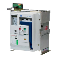
Figure 31. Slide reset lever and spring on the mounting plate.
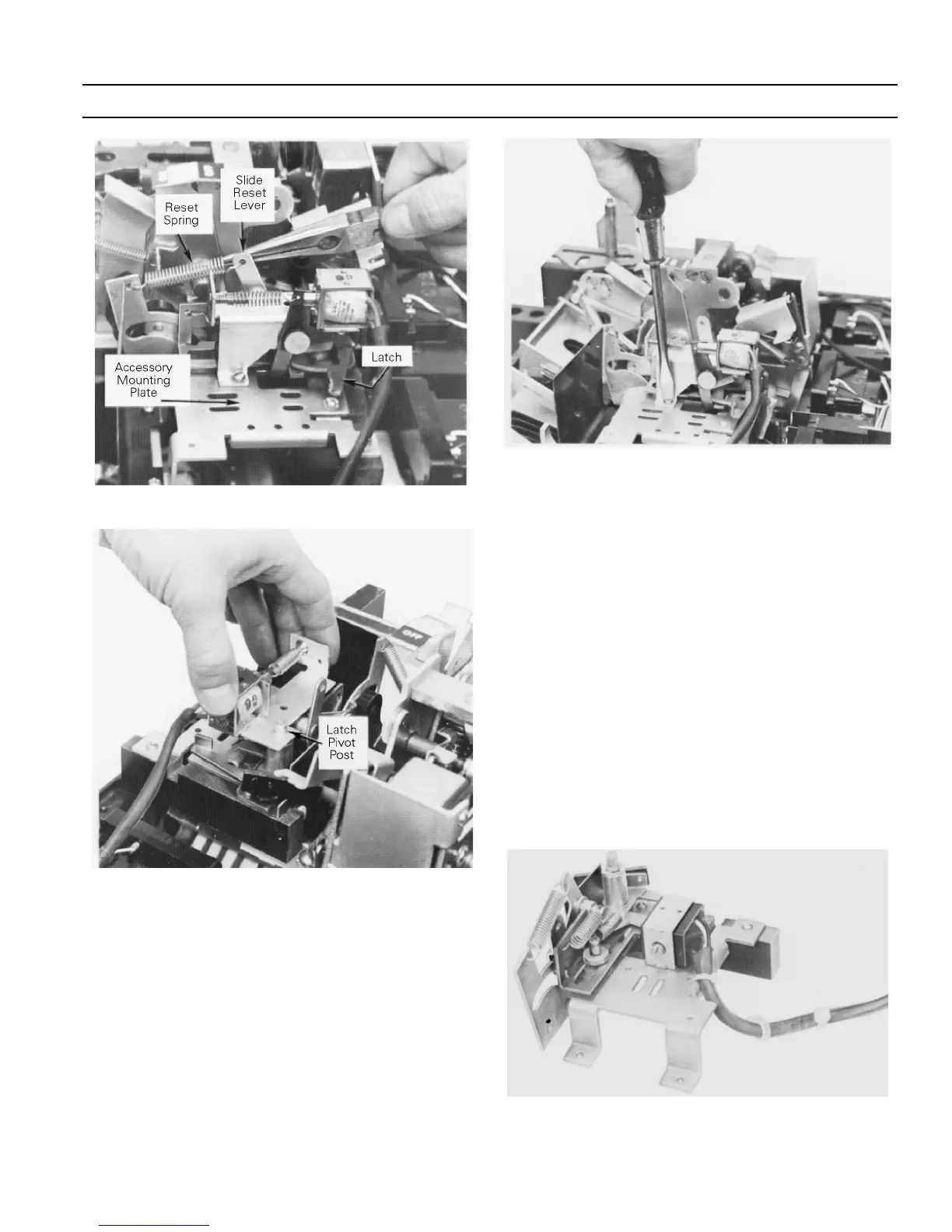
Figure 32. Positioning the UVR assembly on the mounting plate.
11
11
00
00
..
..
Use the wire ties provided to secure the leads to the
mounting plate and to secure the wire bundle to the
inside and outside of the breaker base, as shown in
Figure 20.
11
11
11
11
..
..
Reassemble the breaker covers as described in
Breaker Cover Reassembly
.
11
11
22
22
..
..
Mount the dropping resistor (when supplied) and
MOV, shown in Figure 29. Wire these as shown in
Figure 30.
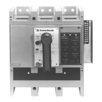
Figure 33. Installing the UVR mounting screw.
11
11
33
33
..
..
Perform the following functional check of the UVR:
aa
aa
..
..
Apply rated voltage to the UVR coil.
bb
bb
..
..
Turn the breaker on.
cc
cc
..
..
Reduce the control voltage. The breaker should
trip when the voltage drops to 35–60% of its rated
value.
11
11
44
44
..
..
Apply the UVR descriptive label to the left side of the
breaker near the lead-exit area.
3–5 Blown-Fuse Trip Device
The blown-fuse trip device (three-coil shunt trip), shown
in Figure 34, is intended for applications with breakers
and fuses in series. This accessory prevents single-phasing
conditions by monitoring the fuses and automatically
tripping the circuit breaker when a fuse blows. It does not
protect from single-phasing of the power source.
Figure 34. Blown-fuse trip device accessory.
 Loading...