18
11.8—Lubrication
Proper lubrication is important for maintaining reliable circuit
breaker performance. The ML-20 mechanism uses bearings
which have a synthetic lining in some locations. These
bearings do not require lubrication to maintain low friction, but
lubrication does not harm them and oiling lightly is
recommended. Sleeve bearings are used in some linkage
locations and needle or roller bearings are used for low friction
on trip shaft and close shaft.
Bearings are lubricated during factory assembly with grease
and oil, but all lubricants have a tendency to deteriorate with
age. Providing a fresh lubricant supply at periodic intervals is
essential to proper breaker operation, especially where
frequent operation may have forced lubricant out of the
bearing surfaces. Apply a few drops of light synthetic machine
oil such as Mobile 1 at each bearing. Apply a coat of
0282A2048P009 grease on the four corners of the closing
spring guide where it enters inside the spring.
Metal-to-metal contact surfaces should be cleaned and
lubricated with 0282A2048P009 grease to provide cleanliness
and prevent oxidation.
Electrical primary contact surfaces also require periodic
lubrication to inhibit oxidation and minimize friction. At each
inspection and maintenance interval, do the following:
1. Wipe clean and coat lightly with grease
(0282A2048P009) all silvered primary contact surfaces
such as the movable contact rod of the interrupter and
the primary disconnect fingers.
2. Clean and coat lightly with grease the pins of the
secondary disconnect coupler.
11.9—Recommended Maintenance
The following operations should be performed at each
maintenance check:
1. Perform a visual inspection of the breaker. Check for
loose or damaged parts.
2. Perform slow closing operation described under
MECHANICAL CHECKING AND SLOW CLOSING.
3. Check the erosion indicator and the wipe and gap as
described under DIMENSIONAL CHECKS.
4. Perform the vacuum interrupter integrity test as
described under ELECTRICAL CHECKS.
5. Lubricate the breaker operating mechanism as described
under LUBRICATION.
6. Check the electrical operation using the test cabinet (if
available) or the test position in the metalclad switchgear.
CAUTION: REPEATED OPERATIONS AT A RATE EXCEEDING
TWO PER MINUTE MAY CAUSE CHARGING MOTOR
OVERHEATING AND SUBSEQUENT MOTOR FAILURE.
7. Examine the movable contact rod of the vacuum
interrupter. With the breaker open, wipe the lubricant off
the rod and examine the silver surface. The rod should
have a burnished appearance without copper appearing
through the silver. If copper is visible at more than one
location per pole, or if the silver plating is torn, the
interrupter assembly should be replaced. Re-lubricate
movable contact rod with 0282A2048P009 grease
8. If desired, perform the additional electrical tests (Megger,
Primary and Secondary High Potential, and Primary Circuit
Resistance). See ELECTRICAL CHECKS.
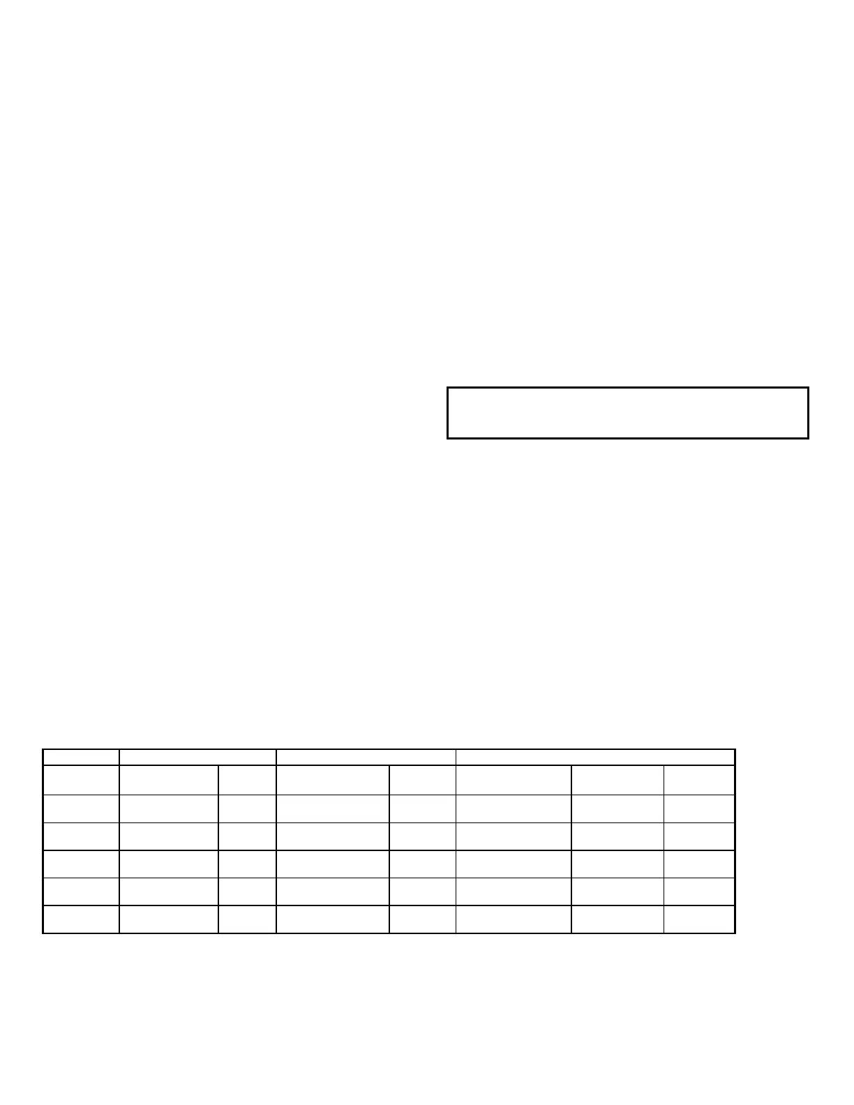
Nominal Charge Motor Close Coil Trip Coil
Control
Voltage
Part No.
Range
Part No.
Range
Part No.
(5 cycle)
Part No.
(3 cycle)
Range
48 VDC 0177C5050G009 36-56 0209B8103G008 38-56 0209B8104G001 0209B8104G0
01
28-56
125 VDC 0177C5050G007 90-140 0209B8103G009 100-140 0209B8104G002 0209B8104G0
07
70-140
250 VDC 0177C5050G008 180-280 0209B8103G010 200-280 0209B8104G003 0209B8104G0
0…6
140-280
120 VAC 0177C5050G047 104-127 0209B8103G011* 104-127 0209B8104G004** N/A (Cap. Trip)
104-127
240 VAC
0177C5050G008
208-254
0209B8103G012*
209-254
0209B8104G004**
N/A
(Cap. Trip)
208-254
*With rectifier
**With Capacitor Trip Module
Table 1. Control Devices and Voltages