GEH-7299A: Installation, Operation and Maintenance Manual
for Type VR1™ Single-Phase, Step Type Regulators
prolec.energy/prolecge 21
4. OPERATION
4.1 Control Interface Instructions
Figure 10. Control Interface
1. To de-energize the electronic control, open the PT switch
and close the CT shorting switch.
2. Disconnect the blue plug from the control module by
pressing the extraction levers on each side.
3. Using a Phillips head screwdriver, remove the four screws
that are used to attach the control module to the adapter
panel.
Note: The current transformer is shorted when the CT shorting switch is closed.
(See diagram 0305E100 sheet 1).
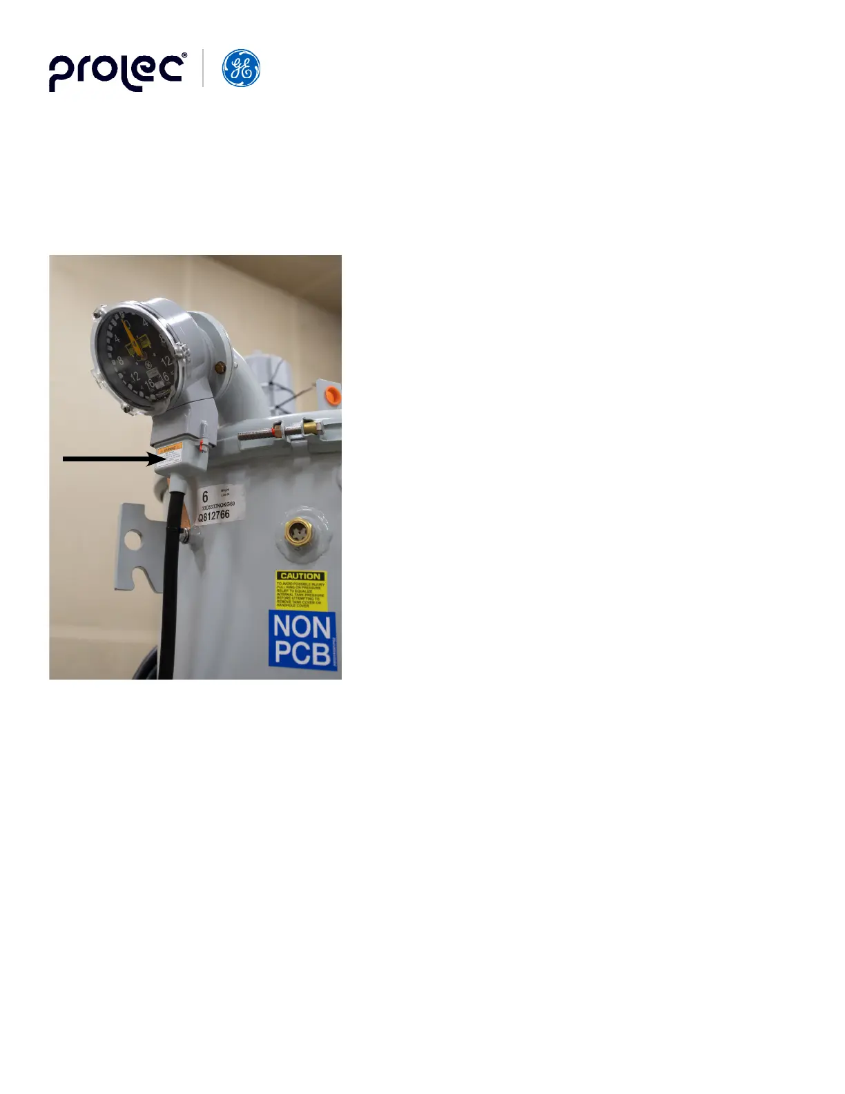
Warning: High Voltage – Current Transformer circuitry. Do not
disconnect the electrical connections inside the housing at the
bottom of the position indicator unless the voltage regulator is
de-energized.
Caution: High Voltage -- Current Transformer circuitry. Do not
energize the voltage regulator unless the control and the current
transformer shorting device in the control are connected.
The control cabinet is designed to remain in place for service of
the electronic control. A disconnect switch mounted in the control
cabinet short circuits the current transformer when the switch is
closed.

 Loading...


