GEH-7299A: Installation, Operation and Maintenance Manual
for Type VR1™ Single-Phase, Step Type Regulators
prolec.energy/prolecge 23
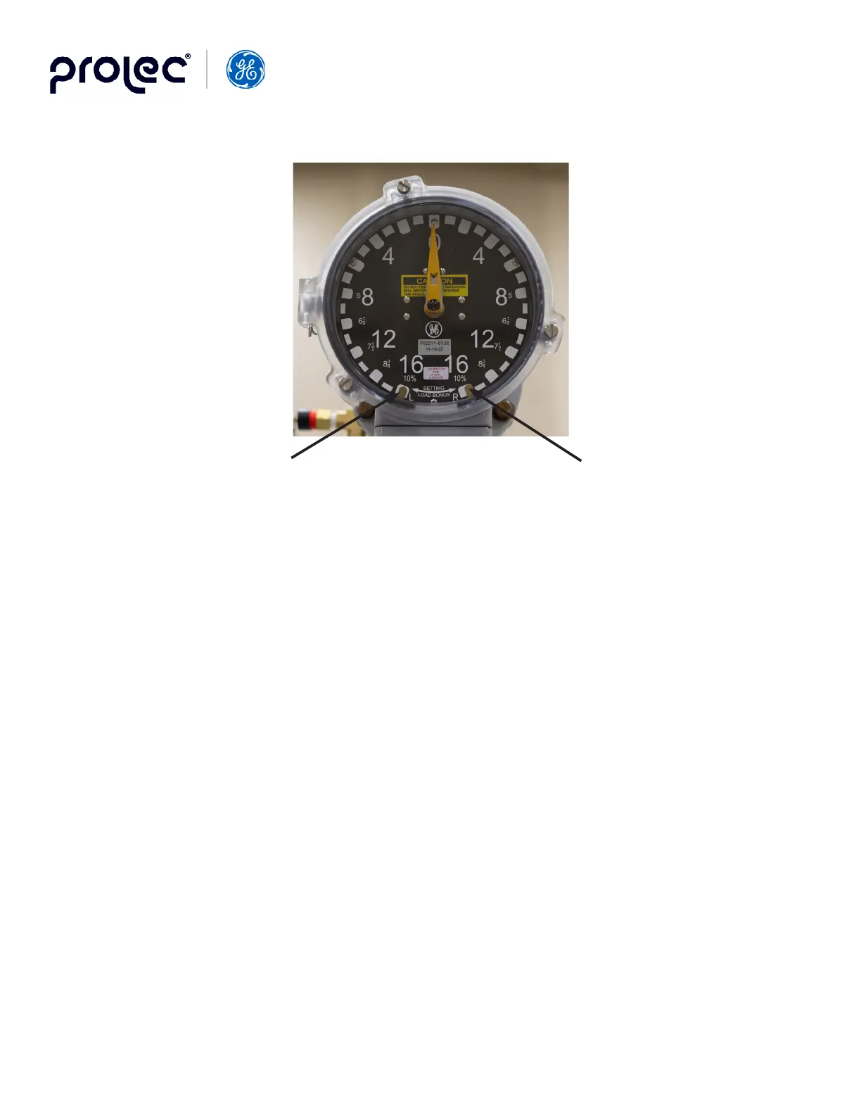
Figure 12. Load-Bonus Position Indicator
4.3 Removing the Indicator Dial Assembly
Warning: Do not remove the indicator dial before deenergizing the regulator.
With the regulator on Neutral, loosen the three screws and open the indicator-glass assembly. Remove the three self-tapping
screws located on the outside perimeter of the dial face. Carefully pull out the dial assembly which contains the pointer,
drag-hand assemblies, and limit switches. The operation counter switch and drag-hand solenoid will be exposed when the
disconnect the leads to the solenoid.
After the dial assembly has been replaced, the indicator pointer should be centered on “0”. To do this, attach one end of the
shaft to “zero-in” the pointer.
5. MAINTENANCE
5.1 Inspecting the Regulator while Energized
At regular intervals, as determined by service, inspect the regulator to make sure it is operating properly and to detect and
To check the operation, it is not necessary to untank the regulator. Run the regulator to its “Raise” and “Lower” limit positions
by using the manual control switch to test the limit switches.
By manual control, run the regulator in either direction a few steps then turn regulator back to AUTO to check the voltage
sensor. After a time delay (30 seconds as set by factory), the tap selector will operate and come to rest.
The devices in the control cabinet require very little maintenance.
Caution: If the electronic control panel is to be removed from the control cabinet for service, the control panel should be
de-energized by opening the PT disconnect switch and closing the CT shorting switch located in the cabinet.
1. Limit Switch Adjusting Knob (Lower)
2. Limit Switch Adjusting Knob (Raise)
21