MDS 05-2708A01, Rev. F MDS TransNET Ref. Manual 71
Pin Descriptions—RS/EIA-422/485 Mode
Table 28 lists the
DATA connector pin functions for radios configured to
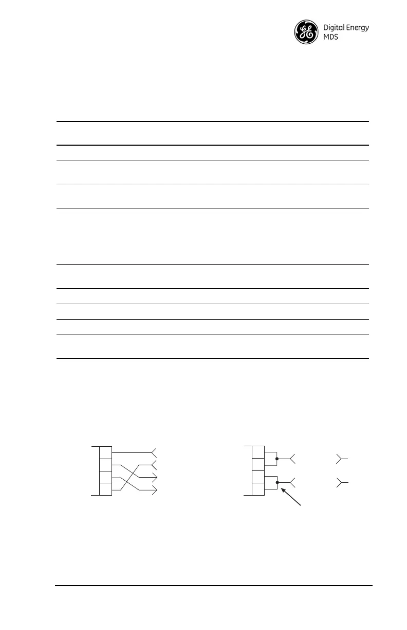
operate in RS/EIA-422/485 mode. See Figure 23 for wiring schemes.
NOTES:
• RXD+ / RXB and RXD– / RXA are data sent to the radio to be transmitted.
• RXD+ / RXB is positive with respect to RXD– / RXA when the line input is a “0”.
• TXD+ / TXB and TXD– / TXA are data received by the radio and transmitted.
• TXD+ / TXB is positive with respect to the TXD– / TXA when the line output is a “0”.
Invisible place holder
Figure 23. EIA-422/485 Wiring Schemes
Table 28. DATA connector pin descriptions—RS-422/485 Mode
Pin
Number
Input/
Output Pin Description
1 — Not Used—Do not connect
2 OUT TXD+/TXA—Non-inverting driver output. Supplies data to
the connected device.
3 IN RXD+/RXA—Non-inverting receiver input. Accepts data
from the connected device.
4 IN Sleep—A ground on this pin turns off most circuits in a Re-
mote radio, including transmit, receive, modem, and diag-
nostic functions. This allows for greatly reduced power
consumption, yet preserves the radio’s ability to be quickly
brought on line. See “Using the Radio’s Sleep Mode (Re-
mote Units Only)” on Page 59 for details.
5 -- Signal Ground (GND)—Connects to ground (negative sup-
ply potential) on the radio’s PC board and chassis.
6 -- Not Used—Do not connect
7 IN RXD– /RXB—Inverting receiving input
8 OUT TXD– /TXB—Inverting driver output.
9 -- Open (User configurable via internal jumper. See
“User Configurable I/O Connections” on Page 73)
EIA-485 2-WIRE CONNECTIONS
TXD
RXD
2
3
7
RADIO
DATA CONNECTOR
8
RXD +
TXD +
EIA-422 4-WIRE CONNECTIONS
RXD/TXD
2
3
7
RADIO
DATA CONNECTOR
8
RXD+/TXD+
EXTERNAL DEVICE
EXTERNAL DEVICE
RXD +
TXD
RXD
TXD +
RXD +
TXD
RXD
TXD +
This jumpering must be provided by user.