Do you have a question about the GE MDS 9710A and is the answer not in the manual?
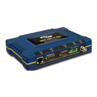
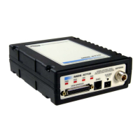
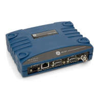
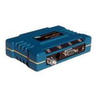
Overview of the MDS 4710/9710 Series digital radio transceivers and their applications.
Details on using transceivers in Point-to-Multipoint (MAS) and Point-to-Point systems.
Explanation of how to interpret the radio's model number for configuration details.
Lists the items included in standard shipments of MDS 4710/9710 transceivers.
Lists optional accessories available for the MDS 4710/9710 transceivers.
Step-by-step instructions for mounting and connecting the transceiver, antenna, and data equipment.
Guidelines and dimensions for physically mounting the transceiver unit.
Recommendations for selecting and installing antennas and feedlines for optimal performance.
Instructions for connecting the transceiver to a power source, including polarity and voltage requirements.
Procedures for ensuring proper grounding to minimize damage and ensure safety.
Details on connecting the transceiver's DATA INTERFACE to DTE equipment using EIA-232.
How to use Sleep Mode for minimal power consumption, especially in solar-powered sites.
Description of the function of each status LED on the transceiver's front panel.
Methods for measuring Received Signal Strength Indication (RSSI) using an HHT or voltmeter.
Basic steps for connecting and starting the GE MDS Hand-Held Terminal (HHT) for programming.
Procedures for re-initializing an HHT for use with the transceiver and configuring its settings.
Information on entering commands using the HHT, including command structure and syntax.
In-depth explanations of user commands for configuring and diagnosing the transceiver.
Using LED status indicators as a troubleshooting tool to identify transceiver issues.
How to read and interpret event codes from the HHT to diagnose system difficulties.
A comprehensive list of event codes reported by the transceiver and their descriptions.
Detailed technical specifications for the MDS 4710/9710 Series transceivers.
Procedures for adjusting helical filters to optimize receive signal strength after frequency changes.
Steps for setting up and performing remote diagnostics on network radios.
How to activate and configure user-programmable I/O pins on the DATA INTERFACE.
Instructions for connecting a PC and using software to upgrade the transceiver's firmware.
Information on installing and using the optional external orderwire module for voice communication.
A chart providing conversions between dBm, Watts, and Volts for RF power expression.
| Frequency Band | 902-928 MHz |
|---|---|
| Data Rate | Up to 115.2 kbps |
| Ethernet Interface | 10/100Base-T |
| Operating Temperature | -30°C to +60°C |
| Power Supply | +10 to +30 VDC |
| Serial Interface | RS-232 |
| Approvals | FCC Part 15 |
| Output Power | 1 W |
| Interface | RS-232, Ethernet |
| Receiver Sensitivity | -110 dBm for 12 dB SINAD |
| Sensitivity | -110 dBm for 12 dB SINAD |