MDS 05-3305A01, Rev. E MDS 4710/9710 Technical Manual 39
4. Use the DLINK ON and DLINK [baud rate] commands to configure the
diagnostic link protocol on the RJ-11 port of each node radio.
5. Connect same-site radios using a null-modem cable at the radios’
diagnostic ports.
6. Connect a PC with GE MDS InSite software installed to the root
radio, or to one of the nodes, at the radio’s DIAG port (this PC can
also be the PC used to collect payload data, as shown in Figure 13).
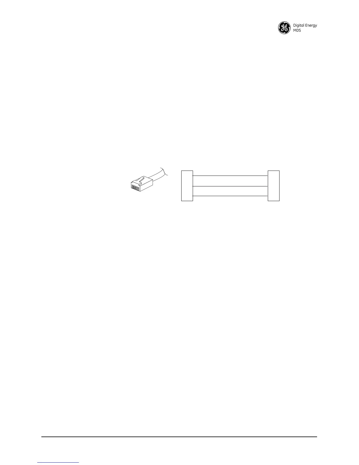
To connect a PC to the radio’s DIAG port, an RJ-11-to-DB-9 adapter
(MDS P/N 03-3246A01) is required. If desired, an adapter cable can
be made using the information shown in Figure 14.
Invisible place holder
Figure 14. RJ-11 to DB-9 Adapter Cable
7. Start the GE MDS InSite application at the PC (see the GE MDS
InSite User’s Guide for instructions).
6.4 User-Programmable Interface Output
Functions
You can manually activate two pins of the DATA INTERFACE using
GE MDS’ InSite NMS software. These two outputs (#1–Pin 22 and
#2–Pin 15) can be connected to compatible user-provided data devices.
The pins provide either a logic high or low depending on the last com-
mand from the
USER I/O SETTINGS in the Network Wide Radio Configuration
screen of InSite. In this InSite window, clicking the SET button sets the
output to high, and clicking on CLEAR sets the output to low. Figure 15
shows the software controls.
One pin on the DATA INTERFACE can be configured as a digital
input. If DIN ON is selected, Pin 16 becomes a digital input. The input is
set when 5 V is applied, and clear when grounded. The same physical
input can be queried as the analog input value on other InSite screens.
RXD
TXD
GND
2
3
5
DB-9 FEMALE
(TO COMPUTER)
TXD
RXD
GND
4
5
6
RJ-11 PLUG
(TO RADIO)
RJ-11 PIN LAYOUT
1
6