QUICK START GUIDE
Below are the basic steps for installing the transceiver. See “INSTALLATION” on Page 5 of this guide for
detailed instructions.
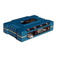
1. Install and connect the antenna system to the radio
• Use good quality, low loss coaxial cable. Keep the feedline as short as possible.
• Preset directional antennas in the direction of desired transmission.
2. Connect the data equipment to the radio’s INTERFACE connector
• Use a DB-25 Male connector to connect to the radio. Connections for typical systems are shown
below.
• Connect only the required pins. Do not use a straight-through RS-232 cable with all pins wired.
• Verify the data equipment is configured as DTE. (By default, the radio is configured as DCE.)
3. Apply DC power to the radio (10.5–16 Vdc @ 2.5 A minimum)
• Observe proper polarity. The red wire is the positive lead; the black is negative.
4. Set the radio’s basic configuration with a Hand-Held Terminal (HHT)
• Set the transmit frequency (TX xxx.xxxx).
• Set the receive frequency (RX xxx.xxxx).
• Set the baud rate/data interface parameters as follows. Use the BAUD xxxxx abc command, where
xxxxx equals the data speed (110–38400 bps) and abc equals the communication parameters as
follows:
a = Data bits (7 or 8)
b = Parity (N for None, O for Odd, E for Even
c = Stop bits (1 or 2)
(Example: BAUD 9600 8N1)
NOTE: 7N1, 8E2 and 8O2 are invalid parameters and are not supported by the transceiver.
5. Verify proper operation by observing the LED display
• Refer to Table 7 on Page 14 for a description of the status LEDs.
• Refine directional antenna headings for maximum receive signal strength using the RSSI command.
DB-9 DB-25 DB-9 DB-25
As required for application
TRANSCEIVER
(DCE)
RTU
(DTE)
DB-9 to DB-25 Example
As required for application
RTU
(DTE)
DB-25 to DB-25 Example
TRANSCEIVER
(DCE)
3
2
7
6
4
8
5
RTS
RXD
TXD
DCD
GND
DSR
CTS
RTS
RXD
TXD
DCD
GND
DSR
CTS
2
3
5
6
7
1
8
2
3
4
5
6
1
7
8
2
3
4
5
6
1
7
8
DSR
TXD
RXD
GND
RTS
CTS
GND
DCD
DSR
TXD
RXD
GND
RTS
CTS
GND
DCD