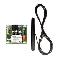
VersaMax* Analog Input, 16-Bit Thermocouple Module
IC200ALG630
October 2016 GFK-1700L
Installation Instructions
The preferred installation technique is to mount the Thermocouple
Module on a Connector-style I/O Carrier and connect thermocouples to
an Interposing Thermocouple Carrier as shown below. The Interposing
Thermocouple-style I/O Carrier provides both box-style wiring terminals
and a built-in thermistor for Local Cold Junction Compensation. It
connects to the Connector-Style Carrier via a cable as shown. This
allows the thermocouple connections to be located away from the I/O
modules in the system. Each TC terminal on the Interposing
Thermocouple Carrier accommodates one solid or stranded AWG #14
(avg. 2.1mm
2
cross section) to AWG #22 (avg. 0.36mm
2
cross section)
wire, or two wires up to AWG #18 (avg. 0.86mm
2
cross section).
However, it is also possible to mount the Thermocouple Module on one
of the terminal-style carriers (box-style, spring-style, or barrier-style) and
provide Local Cold Junction Compensation by using a kit that includes
the correct type of thermistor, as described in the I/O Modules User
Manual. Both methods are shown below. The thermistor kit must be
installed on the A9 and A10 terminals of the carrier.
If the module will only be used to measure millivolt inputs, not
thermocouple inputs, it can be mounted on any type of I/O Carrier. The
thermistor terminals A9 and A10 cannot be used as millivolt input
terminals.
Thermocouple
or Millivolt
Inputs
Thermocouple
or Millivolt
Inputs
Install Optional
Thermistors Here
Built-In Thermistors
Located Here
Installation in Hazardous Locations
EQUIPMENT LABELED WITH REFERENCE TO CLASS I,
GROUPS A, B, C & D, DIV. 2 HAZARDOUS LOCATIONS IS
SUITABLE FOR USE IN CLASS I, DIVISION 2, GROUPS A, B, C,
D OR NON-HAZARDOUS LOCATIONS ONLY
WARNING - EXPLOSION HAZARD - SUBSTITUTION OF
COMPONENTS MAY IMPAIR SUITABILITY FOR CLASS I,
DIVISION 2;
WARNING - EXPLOSION HAZARD - WHEN IN HAZARDOUS
LOCATIONS, TURN OFF POWER BEFORE REPLACING OR
WIRING MODULES; AND
WARNING - EXPLOSION HAZARD - DO NOT DISCONNECT
EQUIPMENT UNLESS POWER HAS BEEN SWITCHED OFF OR
THE AREA IS KNOWN TO BE NONHAZARDOUS.
Field Wiring Terminals
The terminal assignments shown below are the same for all carriers.
Wiring Connections for Carriers with Two Rows of Terminals:
Note: only for thermocouple carrier

 Loading...


