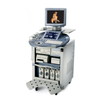
GE HEALTHCARE - KRETZTECHNIK VOLUSON® 730EXPERT (BT03)
D
IRECTION 105899, REVISION 3 DRAFT (APRIL 29, 2008) SERVICE MANUAL
5-18 Section 5-2 - General Information
5-2-6 Description of Hardware Options
5-2-6-1 CW - Continuous Wave Doppler
CW Doppler mode provides real time spectral analysis of CW Doppler signals. This information
describes the Doppler shifted signal from the moving reflectors in the CW Doppler beam. CW Doppler
can be referenced through a small pencil probe or phased array scan head, but it can also be used in
conjunction with a 2D image which has an M-line superimposed on the 2D image indicating the position
of the Doppler sample volume. For through-the-beamformer CW, this beam is steerable by the operator,
and is done by adjusting the location of the M-line. The CW Doppler beam, or M-mode line, can be
steered allowing interrogation along an operator-selected line within the image.
This option can be upgraded by implementing the CW-Dopplerboard (CRW).
5-2-6-2 ECG Preamplifier
MAN6 (internal, digital version)
For details see: Section 5-10-1-1 "ECG-preamplifier (MAN6 - optional)" on page 5-40.
5-2-6-3 MOD (Magneto-Optical Drive)
For details see: Section 5-10-1-3 "Magneto-Optical Drive (optional)" on page 5-40.
5-2-6-4 Scan/Freeze Foot switch
5-2-6-5 Global Modem (optional)
The Multi-Tech global modem is a standard modem that connects to an analog phone line.
It provides high-speed data transfers and fax capabilities. Features like remote configuration, callback
security, and 2-wire leased line support set it apart from basic desktop modems.
In addition, it is approved for use in many countries around the world.
Table 5-3 Hardware Options
HW-Options Description
1
CW-Doppler 5-2-6-1 CW - Continuous Wave Doppler
2
ECG Digital Module 5-2-6-2 ECG Preamplifier
3
MOD (Magneto-Optical Drive) 5-2-6-3 MOD (Magneto-Optical Drive)
4
Scan/Freeze Foot switch 5-2-6-4 Scan/Freeze Foot switch
5
Global Modem 5-2-6-5 Global Modem (optional)
Figure 5-6 Foot-switch Connector (e.g., CPN6)
Footswitch connected to Power Supply-Box (below Main Electronic-Box)

 Loading...