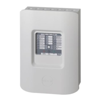
The GE Zenith Controls MX150 Microprocessor Controller is a state-of-the-art device designed for automatic transfer switch (ATS) systems, ensuring a continuous power supply for critical loads. It manages the automatic transfer from a normal power source (S1) to an emergency or alternative power source (S2) when S1 voltage falls below preset limits. The controller is housed on the cabinet door, providing highly accurate control over the transfer switch system.
Function Description
The MX150 controller consists of two main assemblies: the microprocessor board and the LCD and keypad. The microprocessor board, located on the left-hand side of the unit's back, handles customer input/output (I/O) for system interface. This includes engine start relay outputs, pre-signal outputs for transfer (T3, W3, UMD), transfer inhibit inputs (Q3, Q7), remote test inputs (Q2), and network interface (ZNET) input/output.
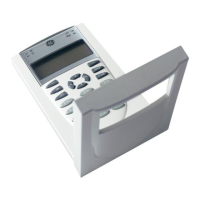
The LCD and keypad, situated on the exterior of the door, provide the user interface. It features LED indicators for source availability (S1 and S2 available) and transfer switch position (S1 or S2 position). The LCD screen displays crucial information such as timer countdowns, event reporting (text), current time, day, and date. The keypad allows users to interact with the system, setting sensors and timers, and configuring logic accessories.
The controller integrates with a Relay/Transformer (R/T) box, which contains relays to energize the transfer mechanism at line voltage and transformers to step down line voltage to control levels for controller input. This isolation protects the MX150 from harmful line transients.
Key functions of the MX150 include:
- Voltage and Frequency Sensing: The controller continuously monitors voltage and frequency for both S1 and S2. Users can set "Fail" thresholds, which trigger the engine start timer (P timer) when voltage or frequency drops below acceptable levels. "Restore" thresholds determine when the system is stable enough to transfer back to a source.
- Timers: A variety of adjustable timers manage the transfer process:
- P (Time Delay Source 2 Start): Delays the start of Source 2.
- W (Time Delay Source 2 Stable): Ensures Source 2 voltage and frequency are stable before transfer.
- T (Time Delay Source 1 Stable): Ensures Source 1 voltage and frequency are stable before retransfer.
- U (Source 2 Stop Delay Timer): Allows the engine generator to run unloaded after retransfer to S1.
- DT (Delayed Transition to S1): Time delay from neutral to S1 position for delayed transition systems.
- DW (Delayed Transition to S2): Time delay from neutral to S2 position for delayed transition systems.
- Exercisers:
- CDT (One Event Timer Exerciser): Allows for scheduled engine exercise (load or no-load) with adjustable duration and frequency (daily, weekly, 14-day, or 28-day cycles).
- CDP (Clock Exerciser): An enhanced version of CDT, allowing for multiple independent no-load exercise periods (up to 7 for daily/weekly/14-day/28-day, and 12 for 365-day cycles) with programmable start times and durations.
- Transfer Commit (S13): Configurable option to commit the transfer switch to Source 2 once the W timer begins, even if S1 power returns, preventing short outages from interrupting the transfer.
- In-Phase Monitor (R50): Restricts live-to-live source transfers unless both sources are within 7 electrical degrees of each other, ensuring smooth transitions. This feature can be bypassed if needed, but with a warning about potential load damage.
- Voltage Imbalance (VI): For three-phase sources, this feature monitors phase voltage ratios and initiates transfer if any phase falls outside selected limits within a specified time window.
- Event Log (EL/P): Records up to 16 events, tracking date, time, reason, and action taken, along with system data like total life transfers, days powered up, and source availability times.
- Auxiliary Contacts (A3, A4): Provide contacts that close when the switch is in Source 2 or Source 1 position, respectively, for external control.
- Disconnect Switch (DS): Inhibits transfer in either direction when in "Inhibit" mode, allowing automatic operation in "Auto" mode.
Usage Features
The MX150 is designed for user-friendly operation through its LCD and keypad. Users can navigate through SET and CFG menus to view or modify settings. Access to these menus requires a six-digit access code, typically found on a white label on the back of the controller.
- Initial Energization: A step-by-step process guides users through verifying system voltage, closing circuit breakers, starting the generator, and checking phase voltages and rotation. LEDs on the control panel indicate source availability and ATS position.
- System Clock: The system clock can be set or adjusted via the SET menu, allowing users to configure the current time, day, and date. A backup battery ensures clock function retention.
- Exerciser Configuration: Both CDT and CDP exercisers can be configured through the CFG menu to set the exercise type (load or no-load) and frequency. The SET menu allows for detailed scheduling of exercise duration and start times.
- Testing: The controller includes a TEST button to initiate various test options:
- XFR LOAD: Starts the generator and transfers the load to Source 2 using current timer settings.
- FAST TEST: Presets timers to a maximum of 30 seconds for quick testing, then resets them to original values.
- NO XFR: Starts the generator but does not transfer the load.
- The test can be canceled or bypassed using dedicated buttons.
- Bypass Timers (YEN): When applicable, the system prompts the user to bypass T or W timers, offering flexibility during operation or testing.
- System Information: The controller provides access to system information such as serial number, software revision, event log, total life transfers, and source availability times through the System Info menu.
Maintenance Features
The MX150 is built for reliability, but regular maintenance is crucial for its longevity and safe operation.
- Inspection and Cleaning: Periodically inspect the switch for dust, dirt, or moisture accumulation. Clean the unit by vacuuming or wiping with a dry cloth or soft brush. Avoid using a blower, as debris can become lodged in electrical and mechanical components. Check the condition of contacts and remove any surface deposits. Replace pitted or worn contacts.
- Mechanical Integrity: Conduct a general inspection for loose, broken, or worn parts.
- Lubrication: The operating mechanism is lubricated with Lubriplate 105 at the factory, providing adequate lubrication for the switch's lifetime. If contamination occurs, clean and reapply lubricant.
- Battery Replacement: The CDT battery (lithium) typically lasts up to 10 years, but a 3-5 year service cycle replacement is recommended. This battery primarily maintains the exerciser memory and does not affect the controller's core operation.
- Periodic Testing: A periodic test of the transfer switch under load conditions is recommended to ensure proper operation, aligning with National Electric Code articles 700 and 701. This involves initiating an electrical transfer test via the TS test switch, observing the timer cycles, and verifying the transfer and retransfer sequences.
- Safety Precautions: Before any installation, adjustment, or removal of transfer switch components, all power must be turned OFF due to hazardous voltage and current. Only GE Zenith Certified technicians or qualified electricians should perform installation and maintenance. When performing hi-pot or dielectric tests on the power section, the control panel plugs must be disconnected from the microprocessor to prevent damage. Both power sources must be disconnected before manual operation of the switch.
The MX150 is designed to be a robust and intelligent controller, providing essential power management for various applications, from emergency standby systems to critical load management.