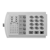
Do you have a question about the GE NX-1308E - Caddx 8 Zone LED Keypad and is the answer not in the manual?
| operating power | 16.5 VAC 25, 40, or 50 VA Transformer |
|---|---|
| auxiliary power with 25 VA transformer | 12 VDC Regulated 500 mA |
| auxiliary power with 40 or 50 VA transformer | 12 VDC Regulated 1 AMP |
| auxiliary power with NX-320E power supply | 12 VDC Regulated 2 AMPS |
| LED keypad current draw | 130 mA max. |
| LED keypad zones normal w/o sounder | 55 mA |
| NX-148E LCD keypad current draw | 110 mA max. |
| NX-148E LCD keypad w/o sounder | 75 mA |
| operating temperature | 32 to 120 degrees F |
|---|
| standard loop resistance | 300 Ohms Maximum |
|---|---|
| 2-wire smokes resistance | 30 Ohms Maximum |
| loop response | Selectable 50mS or 500mS |
| LED keypad width | 6.4" |
|---|---|
| LED keypad height | 4.0" |
| LED keypad depth | 1.1" |
| NX-148E LCD keypad width | 6.4" |
| NX-148E LCD keypad height | 5.3" |
| NX-148E LCD keypad depth | 1.0" |
| metal enclosure width | 11.25" |
| metal enclosure height | 11.25" |
| metal enclosure depth | 3.50" |
| shipping weight | 9 lbs. |
Instructions for physically mounting the control panel board within its enclosure.
Procedures for accessing and exiting the panel's programming interface.
How to enter and interpret numerical values in programming locations.
Programming primary and secondary phone numbers and associated account codes.
Selecting which event types are transmitted to the second phone number.
Selecting which event types are transmitted to the third phone number.
Defining specific parameters for communicator signal formats.
Enabling user-accessible features and communicator reports for Partition 1.
Setting the duration for entry and exit delays for system arming and disarming.
Configuring zone types and partition assignments for zones 1 through 8.
Enabling and configuring siren behavior and system supervision reporting.
Programming the frequency and timing of automatic system tests.
Setting the event code for Contact ID or SIA reports for Zone Type 1.
Enabling features and reports specific to Partition 1.
Configuring zone types and partition assignments for zones 1-8.
Setting durations for various system functions like battery tests and dialer delays.
Defining which partitions trigger auxiliary outputs.
Linking specific events and timings to trigger auxiliary outputs.
Requirements for connecting equipment to the telephone network.
Compatibility information for various country telephone networks.