D
GB
F
E
11
96179-01.2015-DGbFEI
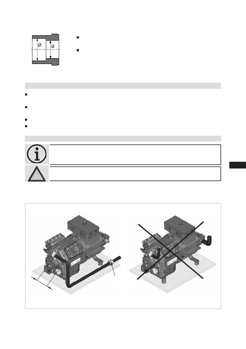
4.5 Laying suction and pressure lines
INFO! Proper layout of the suction and pressure lines directly after the
compressor is integral to the smooth running and vibration behaviour
of the system.
ATTENTION! Improperly installedpipes cancausecracks andtears whichcan
resultinalossofrefrigerant,
A rule of thumb:
Alwayslaytherstpipesectionstartingfromtheshut-offvalvedownwards and
parallel to the drive shaft.
4| Compressor assembly
4.4 Pipes
Pipes and system components must be clean and dry inside and free of scale, swarf and layers of
rust and phosphate. Only use air-tight parts.
Lay pipes correctly. Suitable vibration compensators must be provided to prevent pipes being
cracked and broken by severe vibrations.
Ensure a proper oil return.
Keep pressure losses to an absolute minimum.
The pipe connections have graduated inside diameters so that pipes with
standart millimetre and inch dimensions can be used.
The connection diameters of the shut-off valves are rated for maximum
compressor output. Theactualrequiredpipecrosssectionmustbe
matched to the output. The same applies for non-return valves.
Fig. 10: graduated
internal diameter
Fig. 11
Rigid
fixed point
As short as
possible
 Loading...