2
stop. If the desired setting differs from the factory setting
it can be adjusted as follows: (See diagram)
a. Remove sealing cap (3).
b. Insert enclosed 2mm allen key (2) into adjustment
screw (1).
c. Turn allen key clockwise (+) to increase, or
counterclockwise (-) to decrease pressure setting.
Do not turn adjustment screw more than 3 turns
clockwise (+3).
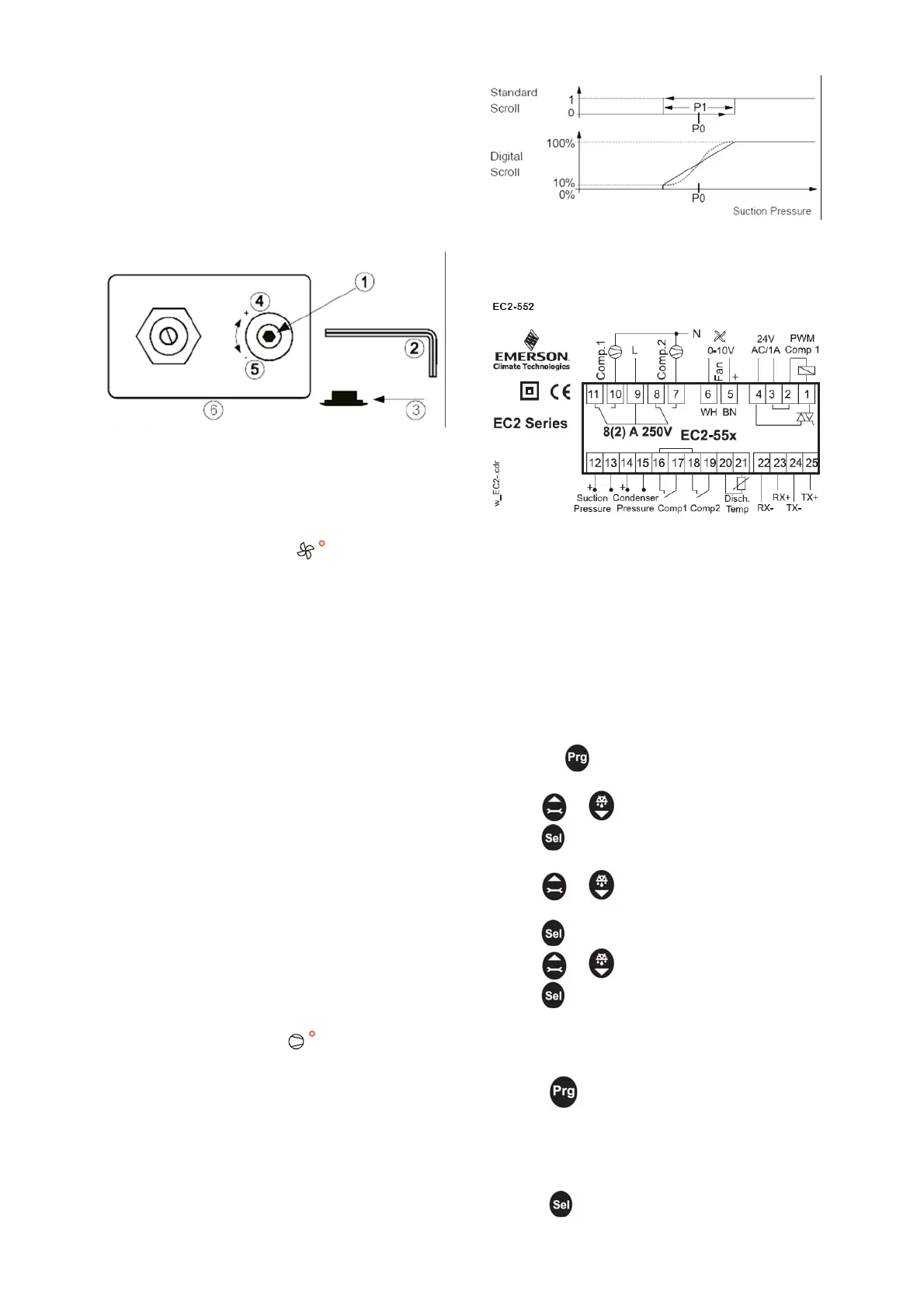
The dead band control loop with dead band ‘P1’
switches the single stage compressors on or off,
1 turn causes a pressure change of approximately 2.6
bar.
Connections to the controller as below, (See wiring
diagrams for further info.)
Adjustment of FSC - Control Point
(Units with EC Fans)
Units fitted with EC fans, listed with electrical option ‘E’
in their part number use the Alco EC552 controller to
monitor and control the head pressure.
The control set point can be adjusted by changing the
parameter P0 in the condensing section of the
controller, ensure the Fan LED “
Set-up / Parameter Modification using the Keypad
” is lit in the display
to avoid accidental adjustment of the compressor set
point. See section F for more information.
The controller is factory set to maintain a suction
pressure of 3.5 BarG on HT units, and 0.8 BarG on LT
units, this can be modified during commissioning as
described below.
d) Compressor Manual Motor Starter/Overload –
Each compressor is supplied via a MMS/Overload,
which should be set to the maximum running current as
shown on the compressor nameplate during
commissioning. In the event of too high a current or
phase loss occurring the MMS will trip out and stop the
compressor, requiring a manual reset.
WARNING: Do not set the controller outside of the
application limits as shown in section 4.
The parameters can be accessed via the 4-button
keypad. The configuration parameters are protected by
a numerical password. The default password is “12”.
Please refer to the parameters table on page 5
To select the parameter configuration:
e) Compressor Contactor – Each compressor supply
is switched via a contactor. The contactor is controlled
via the Compressor Step Controller, and integrates the
compressor safety chain of the HP/LP’s and
MMS/Overloads.
1. Press the
button for more than 5 seconds
2. A flashing 0 is displayed
3. Press or until 12 is displayed; (password)
4. Press
f) Optional Compressor Step Controller – Units with
EC fans and electrical option ‘E’. The starting and
stopping of the compressors is controlled by an
electronic controller (EC2). The controller monitors the
suction pressure via a transducer and brings
compressors in or out to maintain the suction pressure
about the desired setting. Discharge pressure is also
monitored but not used for control purposes unless EC
fans are fitted.
to confirm password
5. The first modifiable parameter code is displayed (/1).
6. Press
or to show the code of the parameter
that has to be changed;
7. Press
to display the selected parameter value;
8. Press
or to increase or decrease the value;
9. Press
to temporarily confirm the new value and
display its code.
To adjust the Suction Target Setpoint modify the ‘P0’
parameter in the compressor section of the controller,
ensure the Compressors LED “
10. Repeat the procedure from point 6 to modify any
other parameters.
” is lit in the display
to avoid accidental adjustment of the condenser set
point. See below for more information.
11. Press
to confirm the new values and exit the
parameters modification procedure.
IMPORTANT : All EC2 controllers are fitted with a
dedicated 24V transformer that is not earthed. The EC2
controllers must not be earthed. Do not fit any other
electrical equipment to the EC2’s transformer.
Temporary Display Of Data:
It is possible to temporarily display the values of the
different sensors. This is a useful feature when initially
setting-up the system without the aid of the WebPages.
Suction Pressure Control EC2-552
2 control loops with the same suction pressure setpoint
‘P0’ modulate the compressors on and off.
Press the
sequentially. The value displayed on the
screen corresponds to the number corresponding to the
 Loading...