immediately, however if the compressor has run for less
than 6 minutes it will be prevented from starting for the
remainder, i.e. if run for 4 minutes, there will be a 2 minute
delay on the next start. This is non adjustable.
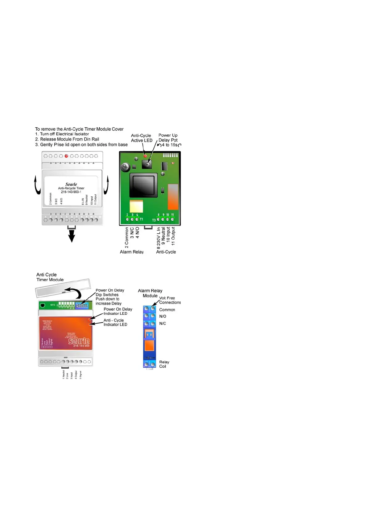
Delay on Power Up start Function
The timer also has an adjustable delay for start up after a
mains power failure. This function may be used to give a
set delay before the compressor starts, and can be set
differently on multiple units to prevent an over current on
the mains supply, and possible tripping of the mains
breaker.
To adjust the delay see the diagrams below.
The modules have indicator LED’s which illuminate when
the delay timer is active.
Units with Combined Alarm Relay and Anti Cycle
Units with separate Anti-Cycle / Alarm Module
h) Volt Free Alarm Relay – Standard on NSQ/NCQ,
optional on NSE NCE, with electrical options W, T & E.
Units are fitted with a volt free relay, either mounted on a
separate din rail, or integrated in the Anti-Cycle timer, (see
section ‘g’). The relay will energise when ‘Healthy’ and will
de-energise on the following faults :-
Mains Power Loss, HP Trip, Compressor Overload Trip.
The relay is a changeover type with volt free terminals for
Normally Open, Normally Closed and Common
connections. Any customer connection to these terminals
must not exceed a load of 8A resistive (AC1) at 230V.
‘L’ version units only
i) DTC - 'LX/S' models use ZF scroll compressors.
ZF model compressors require liquid injection to keep
discharge temperatures within safe limits. The compressor is
equipped with a sensor bulb, which is installed, in the top cap
of the compressor. The bulb senses discharge temperature
and enables controlled liquid injection as temperature rises
above the factory set point. The valve is connected with a
flexible hose to the liquid line via a schraeder connection.
j) Klixon - discharge temperature protector, switches the
compressor off if the discharge temperature exceeds a pre-set
maximum (auto re-set).
k) EVI Vapour Injection Solenoids – ‘LV’ models only.
Units are fitted with a Plate Heat Exchanger to super sub cool
the liquid from the condenser, and provide vapour injection to
the compressors. A solenoid valve on each compressor
vapour injection port is slaved to the compressor contactors
and operates when the compressor runs.
All units
l) Pressure Relief Valve - fitted in the side of the liquid
receiver. If the unit is not located externally in open air the
relief valve outlet must be piped away to open air.
Regular maintenance is required see section 6.
Maintenance Every 3-6 Months.
3. EVACUATION AND CHARGING
Before operating the unit for the first time, check that all
guards, motors, mountings and electrical covers are secure,
and that fans rotate freely. The unit has been leak tested,
dehydrated and filled with a holding charge of "dry air" during
manufacture.
The entire system should be evacuated prior to charging as
follows:
• The right hand panel should be removed to provide access
to the compressor shut off valves with service ports.
• Connect a vacuum pump to the 1/4" flare connections on
each compressor shut-off valve.
• These valves will be in a fully back-seated position in the
unit as supplied. The valve spindles should be screwed in a
few turns to open up the ports.
• Evacuate the system to below 225 microns (0.3mbar). The
pump should be isolated and system pressure monitored. A
rapid continuous rise would indicate a leak in the system.
• During the evacuation process, the crankcase heater
should be switched on.
Note: To ensure that compressor is not operated during
evacuation, the compressor overloads / manual motor starters
must be in the off position.
DO NOT START THE COMPRESSOR UNDER
ACUUM. NEVER RUN COMPRESSOR IF CONTAINING
AIR .
The unit should be charged with the specified refrigerant
(N2CQ ‘L’ Units R404A, ‘N2CQ M’ Units
R404A/R407C/R134A), until the sight glass is just clear at the
normal operating condition. If after charging the unit is left with
the power supply turned off, turn on the power supply for a
minimum period of three hours before the unit is switched on.
This will ensure that the compressor sump is warm and free
from liquid refrigerant.
IMPORTANT
N2CQ Scroll compressors, like several other types of
compressor, will only compress in one rotational direction.
Three-phase compressors will rotate in either direction,
depending upon phasing of the power to T1, T2 and T3. Since
there is a possibility of connecting power in such a way as to
cause rotation in the reverse direction, it is important to check
this. Verification of rotation direction can be made by
observing that suction pressure drops and discharge pressure
rises when the compressor is energised. Reverse rotation
results in a sound level above that of the correct rotation
direction, as well as a substantially reduced current draw.
4
 Loading...