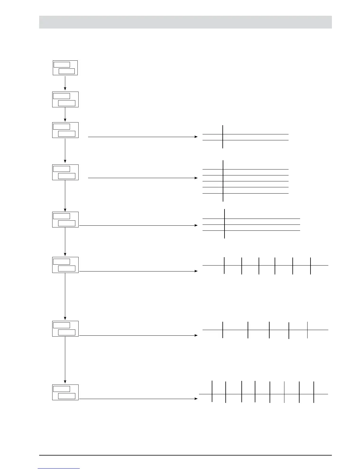
SEr Serial communication Fifth menu to set up
This menu makes it possible to configure the various parameters that control serial communication between the
controller and the supervisor.
Instrument identification code
[0 ... 247]
Serial interface protocol
[0 ... 1]
PV
SV
E
S
R
---
PV
SV
A
P
0
r
Parity selection
[0 ... 2]
Select Baudrate
[0 ... 4]
PV
SV
I
S.
24
n
Virtual instrument inputs
[0 ... 63]
PV
SV
0
S.
19
n
Virtual instrument outputs
[0 ... 31]
PV
SV
U.
S.
80
I
Virtual instrument user interface
[0 ... 255]
Interf LED KEYB DISL DISH LED LED LED LED
1/2/3 OUT4 OUT3 OUT2 OUT1
Bit 7 6 5 4 3 2 1 0
Ex 0 1 0 1 0 0 0
0 Set code 80 in S.U.I to manage KEYB and DISH
interface elements via serial line
Outputs OUTW OUT4 OUT3 OUT2 OUT1
Bit 4 3 2 1 0
Ex. 1 0 0 1 1
Set code 19 in S.0V to manage OUT1, 2 and W
outputs via serial line
Inputs IN2 IN1 PV AL3 AL2 AL1
Bit 5 4 3 2 1 0
Ex. 0 1 1 0 0 0
Set code 24 om S.in to manage PV and IN1 inputs via
serial line
PAR Parity
0 No parity
1 Odd
2 Even
BAV Baudrate
0 1200
1 2400
2 4800
3 9600
4 19200
SR.P Serial protocol
0 CENCAL Gefran
1 MODBUS RTU
PV
SV
o
G
d
1
PV
SV
r.
S
P
1
PV
SV
A.
b
n
4
22
81801G_MHW_1200-1300_07-2011_ENG
 Loading...