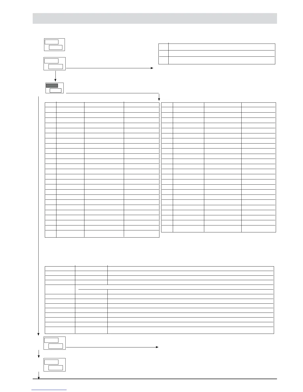
InP Input settings third menu to set up
This menu makes it possible to configure the parameters for the Controller input signals.
PV
SV
P.
S
0
r
0
tYP
PV
SV
PV
SV
n
I
P.
---
Def. remote setpoint
[0 ... 1]
SP.R Type of remote setpoint, Absolute / Relative
0 Digital (from serial line) Absolute
1 Digital (from serial line) Relative to SP or SP1 or SP2 sets
By adding +2 to the value set out in the table, the Set Gradient
(the G.SP parameter of the menu [FG) is expressed in digit/sec.
Probe type, signal, enable custom linearization, and main input scale
TYP Probe type Without dec. point With dec. point
Probe: TC
0 TC J °C 0/1000 0.0/999.9
1 TC J °F 32/1832 32.0/999.9
2 TC K °C 0/1300 0.0/999.9
3 TC K °F 32/2372 32.0/999.9
4 TC R °C 0/1750 0.0/999.9
5 TC R °F 32/3182 32.0/999.9
6 TC S °C 0/1750 0.0/999.9
7 TC S °F 32/3182 32.0/999.9
8 TC T °C -200/400 -199.9/400.0
9 TC T °F -328/752 -199.9/752.0
28 TC CUSTOM CUSTOM
29 TC CUSTOM CUSTOM
30 PT100 °C -200/850 -199.9/850.0
31 PT100 °F -328/1562 -199.9/999.9
32 JPT100 °C -200/600 -199.9/600.0
33 JPT100 °F -328/1112 -199.9/999.9
34 PTC °C -55/120 -55.0/120.0
35 PTC °F -67/248 -67.0/248.0
36 NTC °C -10/70 -10.0/70.0
37 NTC °F 14/158 14.0/158.0
38 0...60 mV -1999/9999 -199.9/999.9
39 0...60 mV
Linear custom Linear custom
40 12...60 mV -1999/9999 -199.9/999.9
41 12...60 mV
Linear custom Linear custom
TYP Probe type Without dec. point With dec. point
Probe: TC
42 0...20 mA -1999/9999 -199.9/999.9
43 0...20 mA Linear custom Linear custom
44 4...20 mA -1999/9999 -199.9/999.9
45 4...20 mA
Linear custom Linear custom
46 0...10 V -1999/9999 -199.9/999.9
47 0...10 V
Linear custom Linear custom
48 2...10 V -1999/9999 -199.9/999.9
49 2...10 V
Linear custom Linear custom
50 0...5 V -1999/9999 -199.9/999.9
51 0...5 V
Linear custom Linear custom
52 1...5 V -1999/9999 -199.9/999.9
53 1...5 V
Linear custom Linear custom
54 0...1 V -1999/9999 -199.9/999.9
55 0...1 V
Linear custom Linear custom
56 200 mV...1 V -1999/9999 -199.9/999.9
57 200 mV...1 V
Linear custom Linear custom
58 Pers.. 10V-20mA -1999/9999 -199.9/999.9
59 Pers. 10V-20mA
Linear custom Linear custom
60 Pers. 60 mV -1999/9999 -199.9/999.9
61 Pers. 60 mV
Linear custom Linear custom
62 PT100 – JPT CUSTOM CUSTOM
63 PTC CUSTOM CUSTOM
64 NTC CUSTOM CUSTOM
CUSTOM linearization: the L0 message occurs when the variable assumes values less than the LO.S parameter or the
minimum calibration value. The KI message occurs when the variable assumes values greater than
the K’.S parameter of the maximum calibration value
Maximum Non Linearity Error for Thermocouples (TC), Thermoresistances (Pt100) and Thermistors (PTC, NTC). The error is
calculated as a departure from the theoretic value, referring in % terms to the of full scale value, expressed in degrees Celsius (°C)
PV
SV
L
F
0.1
t
PV
SV
L
F
0.5
d
Probe type Probe Error
Thermocouples TC J, K type < 0,2 % f.s.
TC S, R type with range 0..1750 °C: < 0,2 % f.s. (t > 300 °C); for other ranges: < 0,5 % f.s.
TC T type < 0,2 % f.s. (t > -150 °C)
Using a Custom Linearization:
TC E, N, L type < 0,2 % f.s.; E type range 100..750 °C; N type range 0..1300 °C; L type range 0..600 °C
TC B type with range 44..1800 °C: < 0,5 % f.s. (t > 300 °C)
TC U type with range -200..400 °C: < 0,2 % f.s. (t > -100 C°)
TC G type < 0,2 % f.s. (t > 300 °C)
TC D type < 0,2 % f.s. (t > 200 °C
TC C type with range 0..2300 °C: < 0,2 % f.s.
Thermistors NTC < 0,5 % f.s.
JPT100 / PTC < 0,2 % f.s.
Thermoresistances Pt100 with range -200..850 °C: precision better than 0.2 % f.s.
Digital filter on input
[0.0 ... 20.0] sec
If set to “0”, the medium filter on the sample value is
excluded
Digital filter on input display
[0 ... 9.9] scale points
23
81801G_MHW_1200-1300_07-2011_ENG
 Loading...