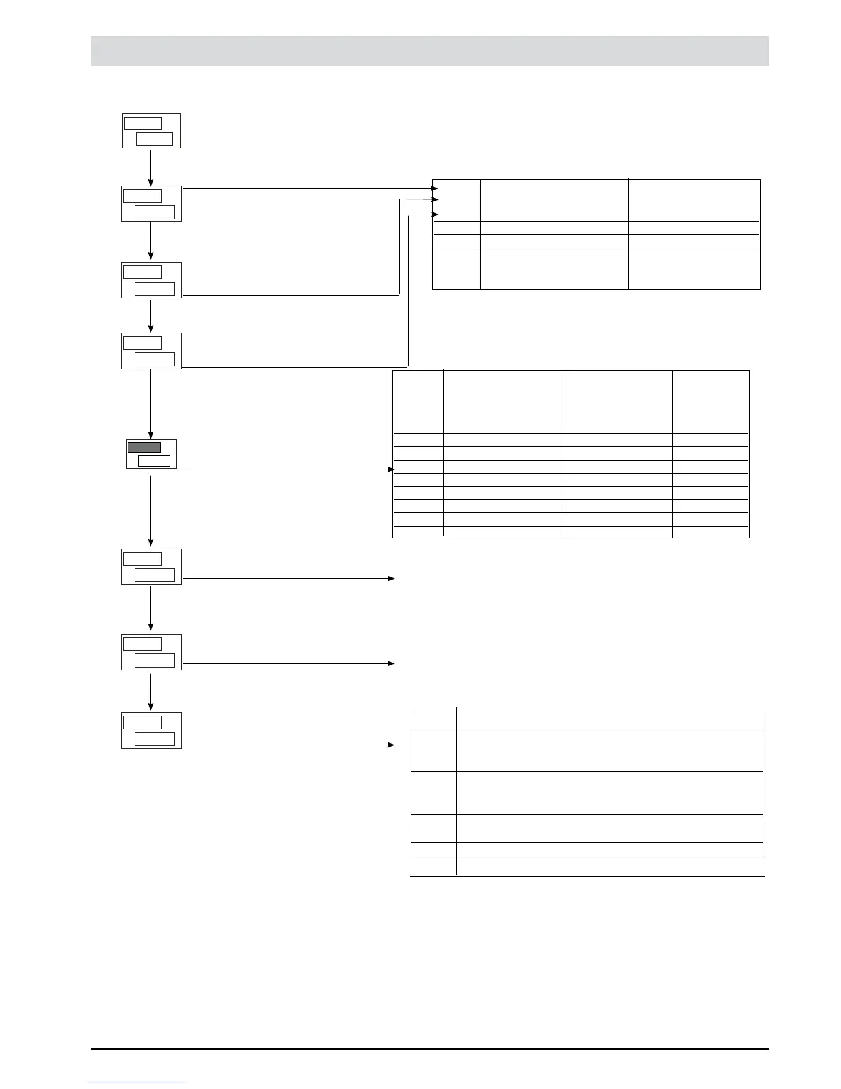
0VT Output settings Second menu to set up
This menu makes it possible to configure the parameters of the Controller outputs.
PV
SV
i.
A
0
r
PV
SV
2.
A
0
r
Select reference signal for alarm
1
Select reference signal for
alarm 2
PV
SV
v
0
t
---
PV
SV
3.
A
0
r
0
AI.t
PV
SV
Alarm type 1
Select reference signal for alarm 3
PV
SV
3.
A
0
t
Alarm type 3
HB alarm function
PV
SV
2.
A
0
t
Alarm type 2
A 1.R
A2.R
A3.R Variable to compare Alarm setpoint
0 PV (process variable) AL
1 SV (active setpoint) AL only absolute
2 PV (process variable) AL only realtive and
referred to SP
(with multiset function)
A1.T Direct
A2.T (high limit) Normal
A3.T Inverse (low limit) Absolute/Relative Symmetrical
to active setpoint (window)
0 Direct Absolute Normal
1 Inverse Absolute Normal
2 Direct Relative Normal
3 Inverse Relative Normal
4 Direct Absolute Symmetrical
5 Inverse Absolute Symmetrical
6 Direct Relative Symmetrical
7 Inverse Relative Symmetrical
By adding the following figures to the value in the table it is possible
to enable a series of supplementary functions:
+8: to disable on power up until first interception
+16: to latch alarm.
+32: KY.1 (2 / 3 ) menu [FG = delay time for alarm trip [0..999] sec.
(excluding symmetrical absolute)
+64: KY.1 (2 / 3 ) menu [FG = delay time for alarm trip [0..999] min.
(excluding symmetrical absolute)
KB.F Function description
0 Relay, logic output: alarm active on load current level
lower than setpoint during the ON time of the control
output.
1 Relay, logic output: alarm active on load current level
higher than setpoint during the OFF time of the control
output.
2 Alarm active if one of functions 0 and 1 is true
(OR logic (*)
3 Continuous heat alarm (**)
7 Continuous cool alarm (**)
By adding the following figures to the value in the table it is possible to
enable a series of supplementary functions:
+0: assigned to output OUT1 (only for KB.F = 0,1,2).
+4: assigned to output OUT2 (only for KB.F = 0,1,2).
+8: assigned to output OUT3 (only for KB.F = 0,1,2).
+12: assigned to output OUT4 (only for KB.F = 0,1,2).
+16: inverse HB alarm.
NOTE: The HB alarm is disabled if assigned to a rapid output (except
codes 3 and 7)
*) minimum setting is fixed at 12% of amperometric full scale
**) cAs type 0 without reference to cycle time
PV
SV
b.
K
4
F
25
81801G_MHW_1200-1300_07-2011_ENG
 Loading...