PV
SV
L.
r
2
1
PV
SV
L.
r
3
3
PV
SV
L.
r
4
4
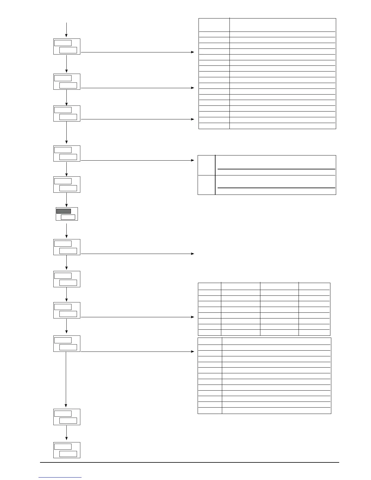
OUT 3
Allocation of reference signal
OUT 4
Allocation of reference signal
PV
SV
L.
r
0
2
PV
SV
t.
G
20
1
20
Gt.2
PV
SV
TCycle time for OUT 2 (HEAT or COOL)
[1 ... 200] seg. ( [0.1 ... 20.0] sec.)
Cycle time for OUT 1 (HEAT or COOL)
[1 ... 200] sec.
OUT 2
Allocation of reference signal
PV
SV
t.
G
20
4
PV
SV
E
r
0
l
Cycle time for OUT 4 (HEAT or COOL)
[1 ... 200] sec.
Fault action (sets state in case of probe
fault) Err, Sbr
PV
SV
t.
G
20
3
PV
SV
n.
A
0
o
OUT W
Allocation of signal or reference value
Cycle time for OUT 3 (HEAT or COOL)
[1 ... 200] sec.
OUT 1
Allocation of reference signal
0VT
PV
SV
A
L.
0
n
Minimum limit of analogue repetition signal
output
[-1999 ... 9999]
Minimum limit of analogue repetition signal
output
[-1999 ... 9999]
RL.1; RL.2
RL.3; RL.4 Function
0 HEAT (control output for heating)
1 COOL (control output for cooling)
2 AL1 – alarm 1
3 AL2 – alarm 2
4 AL3 – alarm 3
5 AL. HB – HB alarm
6 LBA – LBA alarm
7 IN – repetition of logic input 1
8 Repeat but key (if BVT menu KRD = 8)
9 AL1 or AL2
10 AL1 or AL2 or AL3
11 AL1 And AL2
12 AL1 and AL2 and AL3
13 AL1 or AL. HB
14 AL1 or AL2 or AL. HB
15 AL1 and AL. HB
16 AL1 and AL2 and AL. HB
Add +32 to the values indicated in the table to obtain the denied
logic level in output, except for codes 0..1 with continuous output
64 * RL.2 HEAT: heat control output with fast cycle time
(0.1 ... 20.0 sec.)
RL.3 HEAT: continuous output 2 – 10 V
65 * RL.2 COOL: cool control output with fast cycle
time (0.1 ... 20.0 sec.)
RL.3 COOL: continuous output 2 – 10 V
*) only for RL.3 o RL.2 if continuous OUT3 is not present
0.1 sec. if OUT3 is a continuous type output, [T.3 does not
appear in the configuration
REL Alarm 1 Alarm 2 Alarm 3
0 OFF OFF OFF
1 ON OFF OFF
2 OFF ON OFF
3 ON ON OFF
4 OFF OFF ON
5 ON OFF ON
6 OFF ON ON
7 ON ON ON
AN.O Reference value
0 PV – process variable
1 SSP – active setpoint
2 SP – local setpoint
3 –
4 Deviation (SSP – PV)
5 HEAT (*)
6 COOL (*)
7 AL1 (alarm point)
8 AL2 (alarm point)
9 AL3 (alarm point)
10 –
11 Value acquired from serial line (*)
By adding 16 to code 0, if the input is in an error condition
Err - Sbr the output assumes the minimum trimming value
*) – Fixed scale limits
– Retransmission output not available with ON/OFF
control action
PV
SV
A
K.
1000
n
26
81801G_MHW_1200-1300_07-2011_ENG
 Loading...