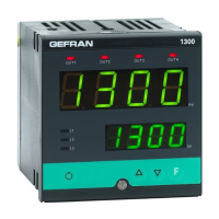
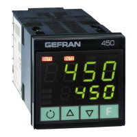
1200/1300
CONTROLLER
cod. 80309 - 01/2014 - ENG
1 • DIMENSIONS AND CUT-OUT; PANEL MOUNTING
This section contains the instructions necessary for
correct installation of the 1200/1300 controllers into the
machine control panel or the host system and for correct
connection of the controller power supply, inputs, outputs
and interfaces.
Before proceeding with installation read the
following warnings carefully!
Remember that lack of observation of these warnings
could lead to problems of electrical safety and
electromagnetic compatibility, as well as invalidating
the warranty.
Electrical power supply
• the controller is NOT equipped with an On/Off switch: the user
must provide a two-phase disconnecting switch that conforms
to the required safety standard (CE marking), to cut off the
power supply upstream of the controller.
The switch must be located in the immediate vicinity of the
controller and must be within easy reach of the operator. One
switch may control more than one controller.
• if the controller is connected to NOT isolated electrical
equipment (e.g. thermocouples), the earth connection must be
made with a specific conductor to prevent the connection itself
from coming directly through the machine structure.
• if the controller is used in applications with risk of damage to
persons, machinery or materials, it is essential to connect it up
to auxiliary alarm equipment. It is advisable to make sure that
alarm signals are also triggered during normal operation.
The controller must NOT be installed in flammable or explosive
environments; it may be connected to equipment operating
in such atmospheres only by means of appropriate and
adequate types of interface, conforming to the applicable safety
standards.
Notes Concerning Electrical Safety and
Electromagnetic Compatibility:
CE MARKING:
The instrument conforms to the European Directives 2004/108/
CE and 2006/95/CE with reference to the generic standards:
EN 61000-6-2 (immunity in industrial environment) EN 61000-6-3
(emission in residential environment) EN 61010-1 (safety).
Series 1200/1300 temperature controllers are mainly designed to
operate in industrial environments, installed on the switchboards
or control panels of productive process machines or plants.
Advice for Correct Installation for EMC
Instrument power supply
• The power supply to the electronic equipment on the
switchboards must always come directly from an isolation
device with a fuse for the instrument part.
• The electronic instruments and electromechanical power
devices such as relays, contactors, solenoid valves, etc., must
always be powered by separate lines.
• When the electronic instrument power supply is strongly
disturbed by the commutation of transistor or power units
or motors, an isolation transformer should be used for the
controllers only, earthing the screen.
• It is essential that the plant has a good earth connection:
- the voltage between neutral and earth must not be >1V
- the Ohmic resistance must be <6W;
• If the mains voltage fluctuates strongly, use a voltage stabilizer.
• In the proximity of high frequency generators or arc welders,
use adequate mains filters.
• The power supply lines must be separate from the instrument
input and output ones.
Inputs and outputs connection
• The externally connected circuits must be doubly isolated.
• To connect the analogue inputs (TC, RTD) the following is
necessary:
- physically separate the input cables from those of the power
supply, the outputs and the power connections.
- use woven and screened cables, with the screen earthed in
one point only
• To connect the regulating and alarm outputs (contactors,
solenoid valves, motors, fans, etc.), fit RC groups (resistance
and condensers in series) in parallel to the inductive loads that
operate in Alternating Current.
(Note: all the condensers must conform to VDE (class X2)
standards and withstand a voltage of at least 220V AC. The
resistances must be at least 2W).
• Fit a 1N4007 diode in parallel with the coil of this can be
removed inductive loads that operate in Direct Current.
GEFRAN S.p.A. declines all responsibility for any
damage to persons or property caused by tampering,
neglect, improper use or any use which does not
conform to the characteristics of the controller and to
the indica tions given in these Instructions for Use.
Warnings and instructions for mounting to the panel
Instructions for installation category II, pollution
level 2, double isolation.
• only for low power supply: supply from Class 2 or low voltage
limited energy source.
• the power supply lines must be separate from the controller
input and output ones
• group the instruments together keeping them separate from the
powered part of the relay
• do not install high-power remote switches, contactors, relays,
thyristor power units (especially the “phase angle” type),
motors, etc. in the same switchboard
• avoid dust, humidity, corrosive gasses and heat sources
• do not block the ventilation holes: the working temperature
must be between 0...50°C
• surrounding air: 50°C
• use 60/75°C copper (Cu) conductor only, wire size range 2x No
22 - 14AWG, Solid/Stranded
• use terminal tightening torque 0.5N m
Nominal ambient conditions
Before supplying the Controller with power, make
sure that the mains voltage is the same as that
shown in the last number of the order code.
2 • INSTALLATION & CONNECTION
3 • DESCRIPTION OF FACEPLATE
4 • CONNECTIONS
PWR
Outputs
Out1 - Out2
Inputs
Serial line
Digital inputs /
CT Input
Outputs
Out3 - Out4
1200
Always make the connections using cable types suitable for
the voltage and current limits given in Section 5 - Technical
Specifications.
If the Controller has faston terminals these must be protected and
isolated.
If it has screw terminals, the wires must be attached, at least in pairs
Power Supply
Inputs
+
24V
4..20mA
VT
+
+
+
S
24VVT
+
+
+
+
Standard:
100...240Vac/dc ±10% , max 18VA
Optional:
11...27Vac/dc ±10%, max 11VA 50/60 Hz
Available thermocouples:
J, K, R, S, T
(B,E, N, L, U, G, D, C
possible by inserting a
custom linearization)
- Observe polarities
- For extensions, use the
correct compensating cable
for the type of TC used
Connect for
0/4..20mA
input
Jumper S3 closed on
CPU board (see CAP.
6 Maintenance)
Linear input in
Direct Current
0/4..20mA, Ri = 50W
TC Input
Linear input with 3-wire transmitter
supplied from the instrument
Linear input with 2-wire
Transmitter supplied from the
instrument
~
PWR
Linear input (I)
Inputs
+
Linear input in
Direct Current
60 mV, 1V (Ri > 1MW)
5V, 10V (Ri > 10KW)
Linear input (V) PTC/NTC/Pt100/JPT100 input
T
Jumper S2 closed
on CPU board
(see CAP. 6
Maintenance)
Use wires of
adeguate diameter
(min. 1mm
2
)
2-wire connection 3-wire connection
Outputs Out1, Out 2 User configurable generic outputs
C
NO
NC
- Relay 5A
250Vac/30Vdc
NC not
available if
Out2 is triac
type
Out 1
-
+
C
NO
- Relay 5A
250Vac/30Vdc
- Logic 24V
(10V a 20mA)
Out 2
~
~
load
Triac
20...240Vac,
max. 1A ± 10%
Out 2
Outputs Out3, Out 4 User configurable generic outputs
Out3
+
- Relay 5A 250Vac/30Vdc
- Logic 24V 10V a 20mA
- Direct 0...10V, 0/4...20mA
- Analogue 0...10V, 0/4...20mA
- 0/2...10V (S1-ON),
0/4...20mA (S1-OFF)
S1 is a jumper on the board
for continuous or analogic
output
Out 3
Out4
+
- Relay 5A 250Vac/30Vdc
- Logic 24V (10V a 20mA )
Out 4
T
S1
Digital inputs / CT Input User configurable generic inputs
IN2
IN1
COM
Digital input 24V 5mA
(Jumpers S1, S2 in position P)
or from non-powered terminal
(Jumpers S1, S2 in position N)
Hrd Menù configuration
Parameter diG or di2 = +16
IN1, IN2 digital inputs
TA
IN1
COM
- Input from current transformer
50mAac, 10W 50/60Hz
- Digital input 24V 5mA
(Jumpers S1, S2 in position P)
or from non-powered terminal
(Jumpers S1, S2 in position N)
Hrd Menù configuration
Parameter diG or di2 = +16
CT, IN1 inputs
S1
S2
N P
S1
S2
N P
1200
A
1300
A
For correct and safe installation, follow the instructions and observe the warnings contained in this manual.
(A) panel fixing brackets
Panel mounting:
To fix the unit, insert the brackets provided into the seats on either side of the case.
To mount two or more units side by side, respect the cut-out dimensions shown in the drawing.
Serial line
(data +)
(data -)
GND
B
A
RS485 isolated serial line
Modbus 2 wires (Standard)
Tx
+
Rx
+
RS485 isolated serial line
For configuration
Modbus 4 wires/Cencal.
Modbus 4 wires / Cencal
S1 S1
ID Symbol Function
PV : Shows the process variable, the menu identification, the parameters identification and the error codes
SV : Shows the setpoint value, the value of the parameter displayed in PV and three dashes (- - -) when PV contains a menu
heading
Increases/Decreases the value of the parameter displayed in SV until the max/min. value is reached.
Held down: progressively increases the speed of increasing/decreasing the value displayed in SV.
Used to move between the various menus and parameters of the controller.
Confirms the value of the current parameter (or parameter edited using
) and selects the next parameter.
Button with configurable function: with standard configuration commutes the
controller operating mode (MANUAL/AUTOMATIC).
Is only on when the display
shows the process variable.
(for configuration see parameter BVT in the KRD menu) )
+
Confirms the value of the current parameter (or parameter edited using ) and selects the previous parameter.
Output status indicators:
OUT1 (AL1), OUT2 (Main), OUT3 (HB), OUT4
Function indicators: with standard configuration they show
the controller operating status.
For configuration see parameter LD.1, LD.2, LD.3 in the KRD
L1 MAN/AUTO = OFF (automatic control)
ON (manual control)
L2 SETPOINT 1/2 = OFF (IN1= OFF local Setpoint 1)
ON (IN1=ON local Setpoint 2)
L3 SELFTUNING = ON (Self activated)
OFF(Self deactivated)
INSTALLATION AND OPERATION MANUAL
Side 1 1 Dimensions and cut-out; panel mounting
2 Installation and connection
3 Description of faceplate
4 Connections
Side 2 5 Technical specifications
6 “Easy” programming and configuration
7 Quick start guide
The complete manual is available for download from the
website www.gefran.com
GEFRAN spa reserves the right to make any aesthetic or
functional change at any time and without notice.
Altitude Up to 2000m
Working/storage
temperature
0..50°C/-20...70°C
Non condensing
relative humidity
20...85%