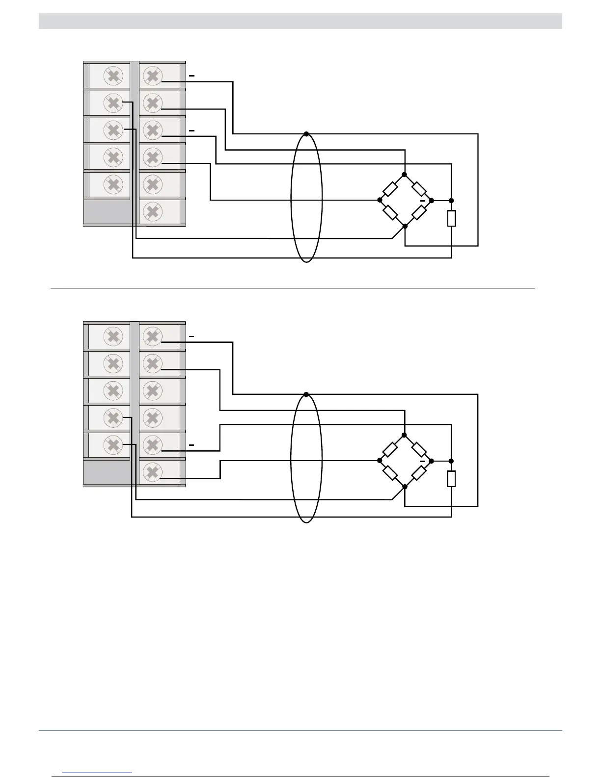
Electrical Connections (Mod. 2500 - 1 - x - x - x - x - x)
N.B.: Respect the probe connections and FASTON “CAL” connections (PROBE imbalance 80%).
FASTON 24 (26) must be connected to the probe at common pin “- EXC”.
Reversal of the “CAL” 80% imbalance leads is indicated at the end of calibration with error signal “Hi”
or “Sbr”.
IN2 Strain-gauge input 4/6 wires
1
24
2
3
4
5
6
25
26
27
28
+
+
+
Probe power supply
5/10V
Green
White
Black or Yellow
Red
Blue
Brown or
Orange
CAL
CAL
- Exc
+ Exc
IN2
IN1 Strain-gauge input 4/6 wires
1
24
2
3
4
5
6
25
26
27
28
+
+
+
Probe power supply
5/10V
Green
White
Black or Yellow
Red
Blue
Brown or
Orange
CAL
CAL
- Exc
+ Exc
IN1
A
A
1380291G_MHW_2500_08-2010_ENG
13 / 77