Do you have a question about the gefran GFX4 and is the answer not in the manual?
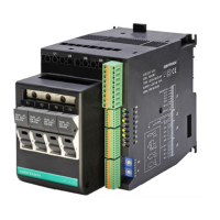
Brief overview of GFX4 controller capabilities, applications, and features.
Essential steps before installation and use to ensure faster start-up and avoid problems.
Guidance on connecting the primary electrical power supply to the controller.
Warnings and conformity details regarding electrical safety and electromagnetic compatibility.
How to connect sensor inputs and output signals.
Procedures for mounting the controller on a DIN guide or panel for proper installation.
Details on connecting the main power supply lines (F1-F4) and load connections (U1-U4).
How to connect sensor inputs (IN1-IN4, IN5-IN8) and digital inputs (DI1-DI2).
Wiring details for auxiliary outputs (O5-O8) and continuous outputs.
Wiring configuration for the power supply and digital inputs DI1 and DI2.
Connection details for auxiliary analog inputs IN5 through IN8.
Wiring guide for analog inputs IN1 through IN4, supporting various signal types.
Explanation of the function of each dip-switch for controller configuration and settings.
Details on Port 1 for local serial communication using the Modbus RTU protocol.
Wiring and connection details for Port 2 using the Modbus RTU fieldbus protocol.
Connection details for Port 2 when using the Profibus DP fieldbus protocol.
Wiring guide for Port 2 when using the CANopen fieldbus protocol.
Connection details for Port 2 when using the DeviceNet fieldbus protocol.
Wiring for Port 2 when using the Ethernet Modbus TCP fieldbus protocol.
Examples of integrating GFX4 modules in various communication network setups.
Examples of connecting single-phase and three-phase loads to the power section.
Adapting serial communication speed and parity for Modbus network modules.
Assigning node addresses for GFX4/GFXTERMO4 to Geflex S1/S2 units.
Technical specifications for analog process inputs IN1 through IN4.
Technical data for digital inputs DI1 and DI2, including configuration options.
Specifications for heat control outputs OUT1 through OUT4 connected to power units.
Specifications for optional cool control outputs OUT5 through OUT8.
Details on the controller's primary serial communication port for local bus.
Information on the controller's optional secondary port for various fieldbus protocols.
Information regarding safety aspects, probe circuit monitoring, and fault detection.
Description of available control actions like PID, on-off, PWM, and autotuning.
Details on the unit's power supply requirements and LED status indicators.
Tables detailing voltage, current, and power ratings for different models and configurations.
Graphs illustrating power dissipation characteristics based on ambient temperature.
Breakdown of the GFX4 controller order code for identifying specific hardware configurations.
Details on available fieldbus protocols and fuse options selectable in the order code.
Information on the Winstrum software and hardware kit for configuration and management.
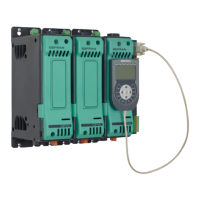
Details on the GFX-OP operator terminal for in-field configuration of the Geflex line.
| Power Supply | 24V AC/DC, 100-240V AC |
|---|---|
| Input channels | 4 |
| Output channels | 4 |
| Operating temperature | 0 to 50°C |
| Protection class | IP20 |
| Input Signal | Thermocouple, RTD, mA, V |
| Output Signal | Relay, SSR |
| Communication | Modbus RTU, Profibus DP, CANopen |
| Number of Phases | Single-phase |
| Control Mode | PID, ON/OFF |
| Voltage Rating | 230V AC |