EasyManua.ls Logo

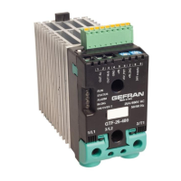
gefran GTF

gefran GTF
36 pages
To Next Page IconTo Next Page
Loading...
180961F_MSW_GTF/GTF-Xtra_07-2018_ENG
ATTENTION!
This manual is an integral part of the product,
and must always be available to operators.
This manual must always accompany the
product, including if it is transferred to another user.
Installation and/or maintenance workers MUST
read this manual and scrupulously follow all of the in-
structions in it and in its attachments. GEFRAN will not
be liable for damage to persons and/or property, or to
the product itself, if the following terms and conditions
are disregarded.
The Customer is obligated to respect trade
secrets. Therefore, this manual and its attach-
ments may not be tampered with, changed, reprodu-
ced, or transferred to third parties without GEFRAN’s
authorization.
CONFIGURATION AND
PROGRAMMING MANUAL
Software version: 2.5x
code: 80961F - 07-2018 - ENG
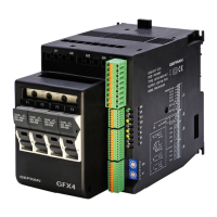
GTF and GTF-Xtra
POWER CONTROLLER
This document is the property of GEFRAN and may not be reproduced or transferred to third parties without authorization.
This document supplements the following manuals:
- Instructions and warnings for GTF/GTF-Xtra
Question and Answer IconNeed help?

Do you have a question about the gefran GTF and is the answer not in the manual?

gefran GTF Specifications

General IconGeneral
Brandgefran
ModelGTF
CategoryController
LanguageEnglish

Summary

Communications and Modbus Network Setup

Modbus Serial Network Installation Guide

A network typically has a Master that "manages" communication by means of "commands" and Slaves that interpret these commands.

Input Signal Configuration and Processing

Main Input Signal Setup

The advanced Solid State Relays have 1 main input to control, to which you can connect, linear sensors in voltage or current to acquire process variable (PV) values.

Digital Input Configuration and Functions

Alarm Management and Configuration

HB ALARM (Heater Break Alarm) Setup

This type of alarm identifies load break or interruption by measuring the current delivered by means of a current transformer.

Power Fault Alarms (Short Circuit, Voltage Loss, Current Loss)

Overheat Alarm Monitoring and Control

Fuse Open and Short Circuit Current Alarms

Overcurrent Fault Protection

Control Modes and Software Functions

Automatic vs. Manual Control Modes

Manages the process variable value and setpoints, freezing them when the digital input is active.

Power Control and Trigger Mode Configuration

SSR Control Modes Overview

The GTF has the following power control modes: PA, ZC, BF, HSC modulation.

Enabling Trigger Modes and Softstart Options

Parameter Hd.5 enables trigger modes like phased, ZC/BF, PA, HSC with softstart options.

Softstart Ramp and Delay Triggering

Feedback Mode Configuration and Calibration

Feedback Calibration Procedure

Feedback calibration can be activated from digital input or serial control, preferably with maximum power.

Enabling and Setting Feedback Modes

Parameter Hd.6 enables feedback modes like None, V², I², P, V (Linear), I (Linear).

Virtual Instrument Control Setup

Related product manuals