EasyManua.ls Logo

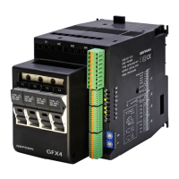
gefran GFXTERMO4 User Manual

gefran GFXTERMO4
78 pages
To Next Page IconTo Next Page
Page #1 background imageLoading...
Page #1 background image
180397M_MSW_GFX4-GFXTERMO4_08-2018_ENG
ATTENTION!
This manual is an integral part of the product,
and must always be available to operators.
This manual must always accompany the
product, including if it is transferred to another user.
Installation and/or maintenance workers MUST
read this manual and scrupulously follow all of the
instructions in it and in its attachments. GEFRAN will
not be liable for damage to persons and/or property, or
to the product itself, if the following terms and condi-
tions are disregarded.
The Customer is obligated to respect trade se-
crets. Therefore, this manual and its attachments may
not be tampered with, changed, reproduced, or trans-
ferred to third parties without GEFRAN’s authorization.
GFX4 / GFXTERMO4
4-ZONE MODULAR POWER CONTROLLER
This document is the property of GEFRAN and may not be reproduced or transferred to third parties without authorization.
LIST OF ATTACHMENTS
This document supplements the following manuals:
- Instructions and warnings for GFXTERMO4
- Instructions and warnings for GFX4
CONFIGURATION AND
PROGRAMMING MANUAL
Software version: 2.1x
code: 80397M - 08-2018 - ENGLISH
Question and Answer IconNeed help?

Do you have a question about the gefran GFXTERMO4 and is the answer not in the manual?

gefran GFXTERMO4 Specifications

General IconGeneral
CategoryController
TypeTemperature Controller
Supply voltage24 V AC/DC
Number of outputs4
Number of inputs2
MountingDIN Rail
DisplayLCD
Protection RatingIP20
Output typeRelay
Input typeThermocouple
CommunicationRS-485
Operating Temperature0°C to 50°C

Summary

CONFIGURATION AND PROGRAMMING MANUAL

INTRODUCTION

SERIAL COMMUNICATION (MODBUS)

GFX-compatible mode

Explains the GFX-compatible Modbus addressing mode.

GFX4 mode

Explains the GFX4 mode Modbus addressing.

ADVANCED SETTINGS

CT AUXILIARY INPUT (Ammeter)

Models with 4 TA

Describes current transformer inputs for 4 TA models.

Models with 1 CT

Describes current transformer inputs for 1 CT models.

AUXILIARY ANALOG INPUT (LIN/TC)

DIGITAL INPUTS

Digital input function assignment

Lists functions assignable to digital inputs.

GENERIC ALARMS AL1, AL2, AL3 and AL4

Alarm setting parameters

Details parameters for setting generic alarms.

Alarm setpoint configuration

Sets the threshold values for the alarms.

GENERIC ALARMS AL1, AL2, AL3 and AL4

Alarm type selection

Configures alarm behavior types.

LBA ALARM (Loop Break Alarm)

LBA alarm configuration

Enables the Loop Break Alarm and sets its parameters.

HB ALARM (Heater Break Alarm)

Heater Break Alarm enabling

Enables the Heater Break Alarm and configures its functions.

Heater Break Alarm setpoints

Sets the setpoints for the Heater Break Alarm.

ALARM SBR - ERR (Probe in short or connection error)

Probe error handling

Configures fault action for probe errors.

Power Fault ALARMS (SSR_SHORT, NO_VOLTAGE, SSR_OPEN and NO_CURRENT)

Power Fault Alarms for GFX4 with 4 TA

Configures power fault alarms for 4 TA models.

Power Fault Alarms for GFX4 with 1 TA

Configures power fault alarms for 1 TA models.

Power Fault ALARMS (SSR_SHORT, NO_VOLTAGE, SSR_OPEN and NO_CURRENT)

Power Fault Alarms for GFXTERMO4 with 4 TA

Configures power fault alarms for GFXTERMO4 4 TA models.

OUTPUTS

Reference signal allocation for outputs

Assigns functions to reference signals for outputs.

Physical output allocation

Assigns functions to physical output channels.

SETPOINT SETTINGS

Local setpoint configuration

Configures the local setpoint value.

Remote setpoint configuration

Sets remote setpoint parameters.

PID HEAT/COOL CONTROL

Heat/Cool control output modes

Describes heat/cool control output configurations.

AUTOMATIC / MANUAL CONTROL

Manual power correction

Allows manual power adjustment based on line voltage.

SELFTUNING

Selftuning activation procedure

Provides steps to activate the selftuning function.

HOT RUNNERS CONTROL

Fault Action Power configuration

Sets power supply during broken probe conditions.

SOFTSTART FOR PREHEATING

Softstart setpoint and power settings

Sets softstart parameters for preheating.

HEATING OUTPUT (Fast cycle)

SSR Control Modes

Describes available SSR control modes.

HETEROGENEOUS power control

VIRTUAL INSTRUMENT CONTROL

INSTRUMENT CONFIGURATION SHEET

GENERIC ALARMS AL1, AL2, AL3 e AL4

GENERIC ALARMS AL1, AL2, AL3 e AL4

Probe error alarms (SBR-ERR)

Handles probe short or connection error alarms.

Heater Break Alarm configuration

Configures the Heater Break Alarm and its setpoints.

ALARMS

PID HEAT/COOL CONTROL

PID parameter settings

Sets PID parameters for heating and cooling.

HOLD FUNCTION

AUTOTUNING

SOFTWARE SHUTDOWN

HEATING OUTPUT (fast cycle)

Related product manuals