30
880397M_MSW_GFX4-GFXTERMO4_08-2018_ENG
HB ALARM (Heater Break Alarm)
This type of alarm identifies load break or interruption by reading the current delivered by means of a current trans-
former.
The following three fault situations may occur:
- delivered current is lower than theoretical current: this is the most common situation, and indicates that a load ele-
ment is breaking.
- delivered current is higher than theoretical current: this situation occurs, for example, due to partial short circuits of
load elements.
- delivered current remains significant even during periods in which it should be zero: this situation occurs in the
presence of pilot circuits for the short-circuited load or due to relay contacts soldered together. In these cases, prompt action
is very important to prevent greater damage to the load and/or to the pilot circuits.
In standard configuration, output OUT1 is associated to heating control in zone 1, obtained by modulating electrical
power with the ON/OFF control based on the set cycle time.
The current read performed during the ON phase identifies an anomalous shift from the rated value due to a load break (first
two fault situations described above), while the current read performed during the OFF phase identifies a break in the control
relay, with consequent output always active (third fault situation).
The alarm is enabled by means of parameter AL.n; select the type of function you want by means of parameter Hb.F:
Hb.F=0: alarm activates if the current load value is below the setpoint value set in A.Hbx while the associated control output
is ON.
Hb.F=1: alarm activates if the current load value is above the setpoint value set in A.Hbx while the associated control output
is OFF.
Hb.F=2: alarm activates by combining functions 0 and 1, considering the setpoint of function 1 as 12% of the ammeter full
scale defined in H.tAx.
Hb.F=3 or Hb.F=7 (continuous alarm): alarm activates due to a load current value below the setpoint value set in A.Hbx; this
alarm does not refer to the cycle time and is disabled if the heating (cooling) output value is below 3%.
Setting A.Hbx = 0 disables both types of HB alarm by forcing deactivation of the alarm state.
The alarm resets automatically if its cause is eliminated.
An additional configuration parameter for each zone, related to the HB alarm is:
Hb.t = delay time for activation of HB alarm, understood as the sum of times for which the alarm is considered active.
For example, with:
- Hb.F = 0 (alarm active with current below setpoint value),
- Hb.t = 60 sec and cycle time of control output = 10 sec,
- power delivered al 60%,
the alarm will activate after 100 sec (output ON for 6 sec each cycle);
if power is delivered at 100%, the alarm will activate after 60 sec.
If the alarm deactivates during this interval, the time sum is reset.
The delay time set in Hb.t must exceed the cycle time of the associated output.
If zone 1 has a 3-phase load, you can set three different setpoints for the HB alarm:
A.Hb1= alarm setpoint for line L1
A.Hb2= alarm setpoint for line L2
A.Hb3= alarm setpoint for line L3
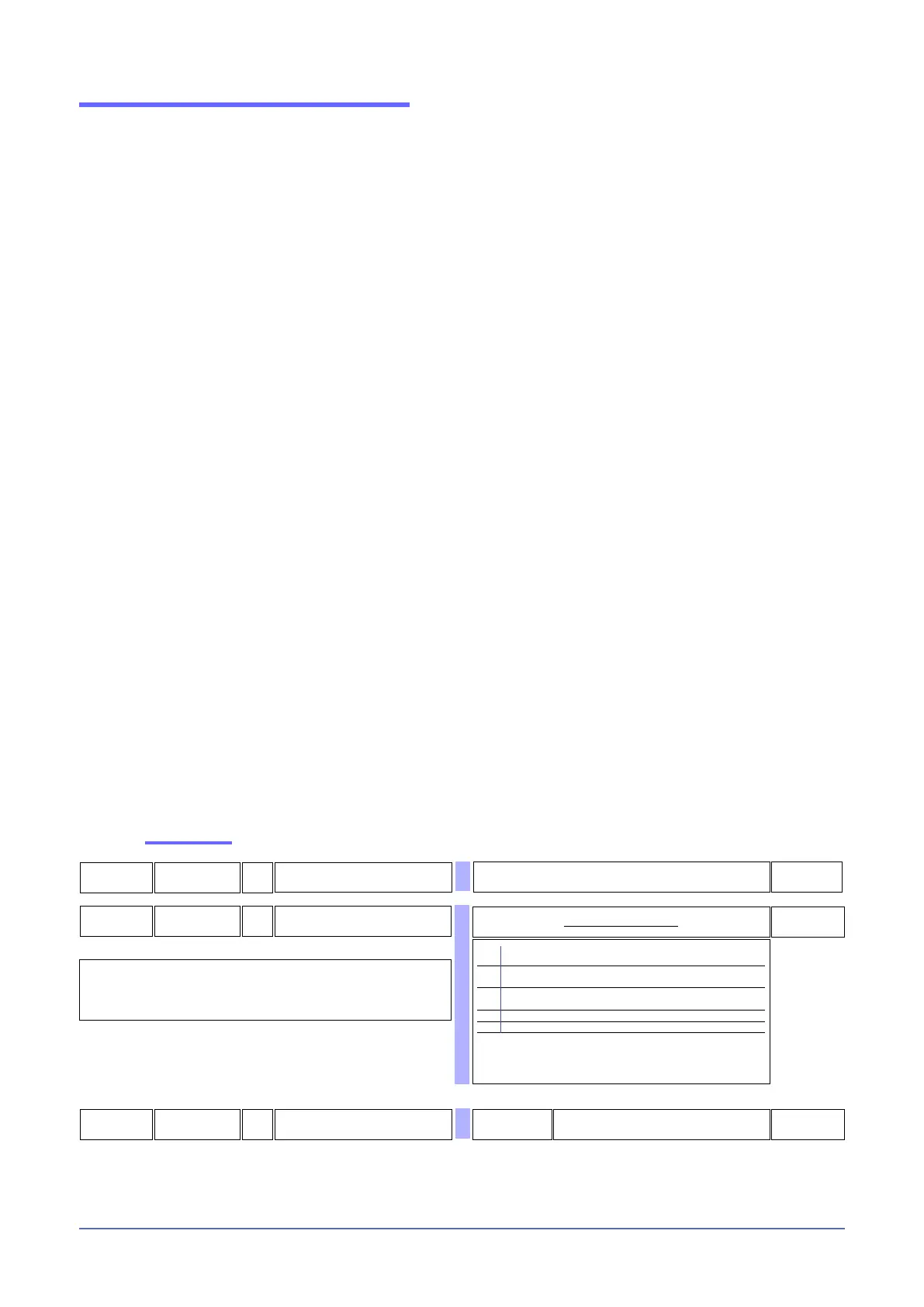
Enable alarm
57
Xb.f
R/W
HB alarm functions
0 Relay, logic output: alarm active at a load current value below
set point for control output ON time.
1 Relay, logic output: alarm active at a load current value above
set point for control output OFF time.
2 Alarm active if one of functions 0 and 1 is active
(OR logic between functions 0 and 1) (*)
3 Continuous heating alarm
7 Continuous cooling alarm
+ 8 HB reverse alarm
+ 16 relates to single setpoints and singled phases WITH 2 and 3-PHASE
LOAD
(*) minimum setpoint is set at 12% of ammeter full scale
Default:
SINGLE-PHASE LOAD: each A.HbX refers to its respective phase.
2-PHASE LOAD: single reference setpoint A.Hb1 and OR between phases 1, 2 and
phases 3, 4.
3-PHASE LOAD: single reference setpoint A.Hb1 and OR among phases 1, 2 and 3.
Table of HB alarm functions
56
XB.T
R/W
Delay time for activation of HB alarm
The value must exceed the cycle time of the
output to which the HB alarm is associated.
0 ... 999 sec
195
AL.n
R/W
Select number of enabled alarms
See: Table of enable alarms
30
0
0