1580961F_MSW_GTF/GTF-Xtra_07-2018_ENG
Enable alarm
5
XB.T
R/W
Delay time for activation of HB alarm
10
The value must exceed the cycle time of the
output to which the HB alarm is associated.
0 ... 999 sec
3
Xb.f
R/W
HB alarm functions
0
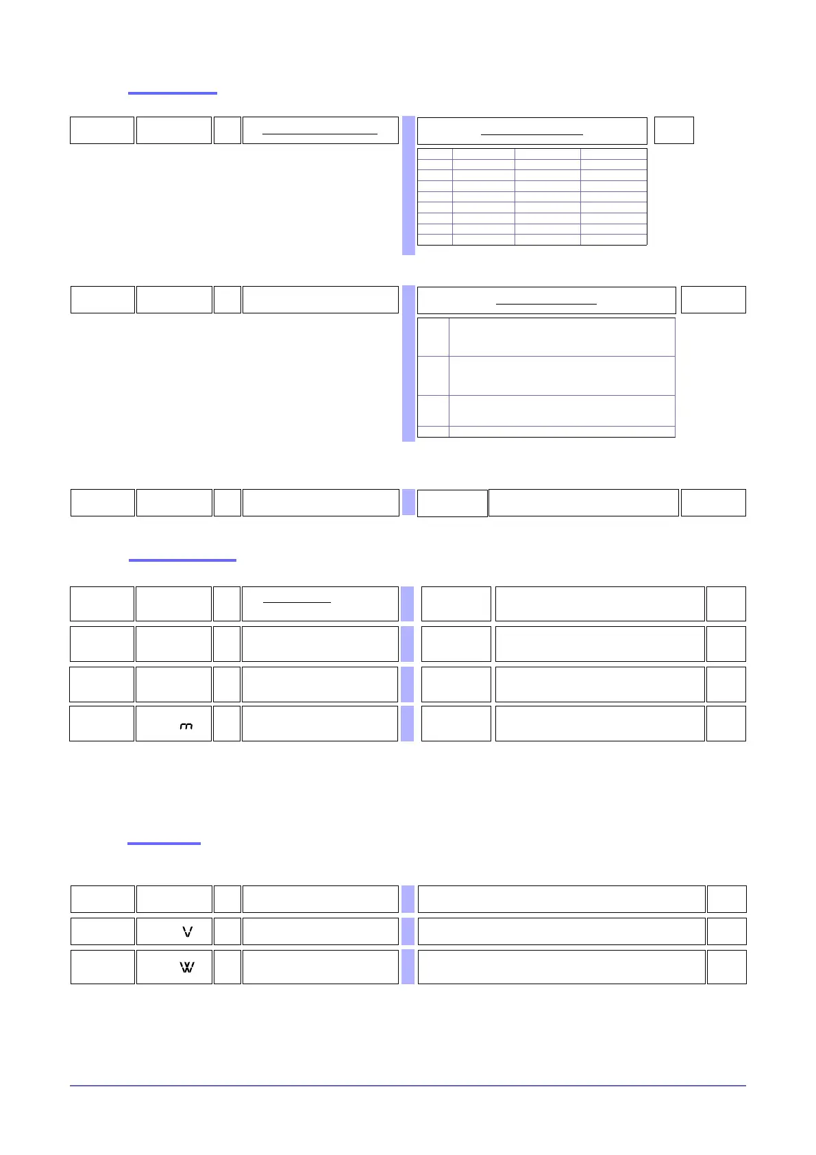
Table of HB alarm functions
0
alarm active at a load current value below
set point for control output ON time.
1
alarm active at a load current value above
set point for control output OFF time.
2
Alarm active if one of functions 0 and 1 is active
(OR logic between functions 0 and 1) (*)
3 Continuous alarm
(*) minimum setpoint is set at 12% of ammeter full scale
+ 8 HB reverse alarm
+32 HB alarm with memory
43
hd.2
R/W
Enable POWER_FAULT alarms
0
Table of Power Fault alarms
SSR_SHORT NO_ VOLTAGE NO_CURRENT
0
1 x
2 x
3 x x
8 x
9 x x
10 x x
11 x x x
+ 32 with memory alarm
+64 for enabling HB alarm
Alarm setpoints
90,0
0
0,0 ... 100,0%
0...1
6
xb.P
R/W
Percentage HB alarm setpoint of
current read in HB calibration
14 bit
Calibration HB
alarm setpoint
for zone
R/W
OFF = Calibration not enabled
ON = Calibration enabled
10,0
L.tA ... H.tA A
4
A.xb
R/W
HB alarm setpoint (scale points
ammeter input)
Read state
0,09
xb.P
R/W
Ou.P power in HB calibration/
0,08
xb.t.
R/W TV read in HB calibration
7
xb.tA
R/W CT read in HB calibration
0,0
100,0
0,0 ... 100,0%
82
xb.P
R/W
Maximum limit with conduction HB
calibration (only for IR lamps)