EasyManua.ls Logo

gefran GFX4

gefran GFX4
35 pages
To Next Page IconTo Next Page
To Previous Page IconTo Previous Page
Loading...
12
80395G_MHW_GFX4_09-2010_ENG
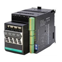
LOAD
LOAD
LOAD
LOAD
1
5
4
3
2
O5
O6
O7
O8
Com 58
V
I
++++
Outputs 5...8 logic/continuous type
Logic outputs 18...36Vdc, max 20mA
Continuous outputs: voltage (default) 0/2...10V, max 25mA
current 0/4...20mA, max 500Ω
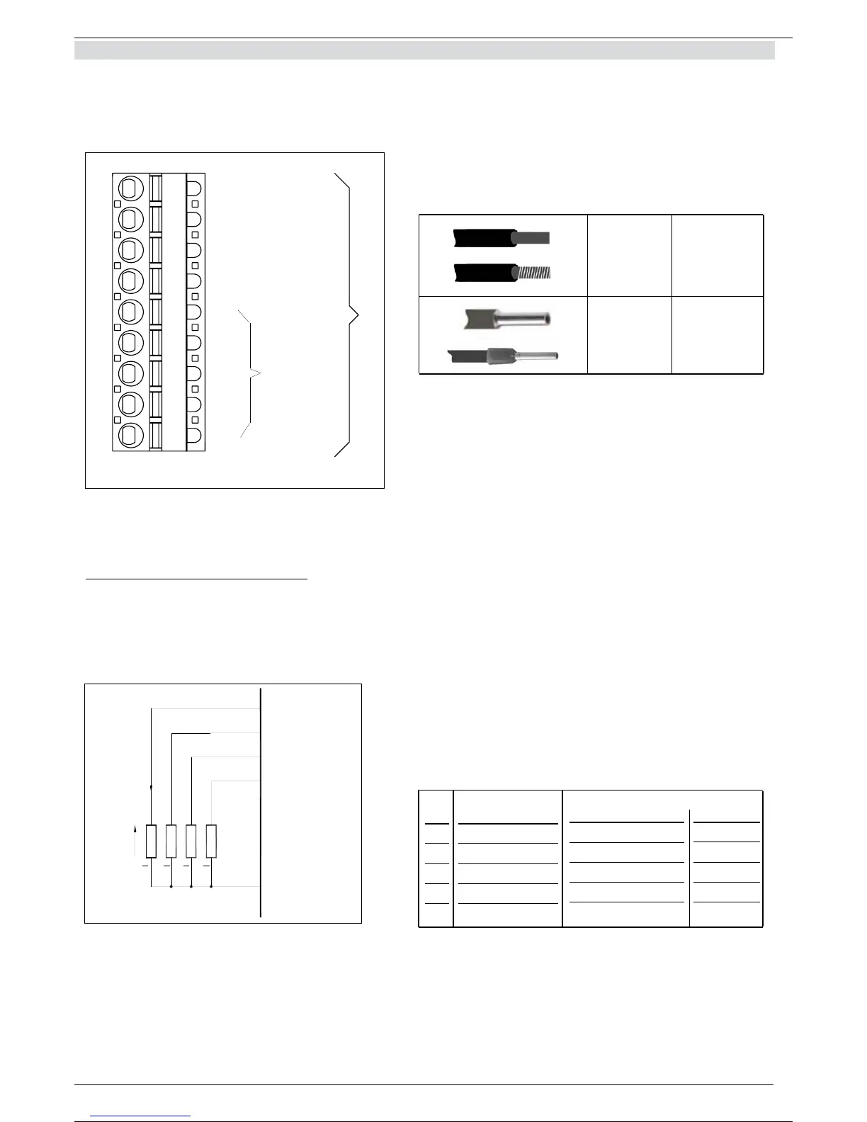
0,2 - 2,5mm
2
24-14AWG
0,25 - 2,5mm
2
23-14AWG
Figure 15 Connector J1
Table 8
Figure 16 Connection scheme for logic/continuous outputs
Table 9
3.3
connector J1 outputs
5...10
1
2
3
4
5
6
7
8
9
If auxiliary outputs (O5...O8), are present, connector J1a becomes J1.
PIN
1
2
3
4
5
Name
Com 5-8
O5
O6
O7
O8
Continuous
(-)
(+)
(+)
(+)
(+)
Logic
Outputs common
Output 5
Output 6
Output 7
Output 8
Description
J1a
J1
12 / 35

Table of Contents

Other manuals for gefran GFX4

Related product manuals