22
80395G_MHW_GFX4_09-2010_ENG
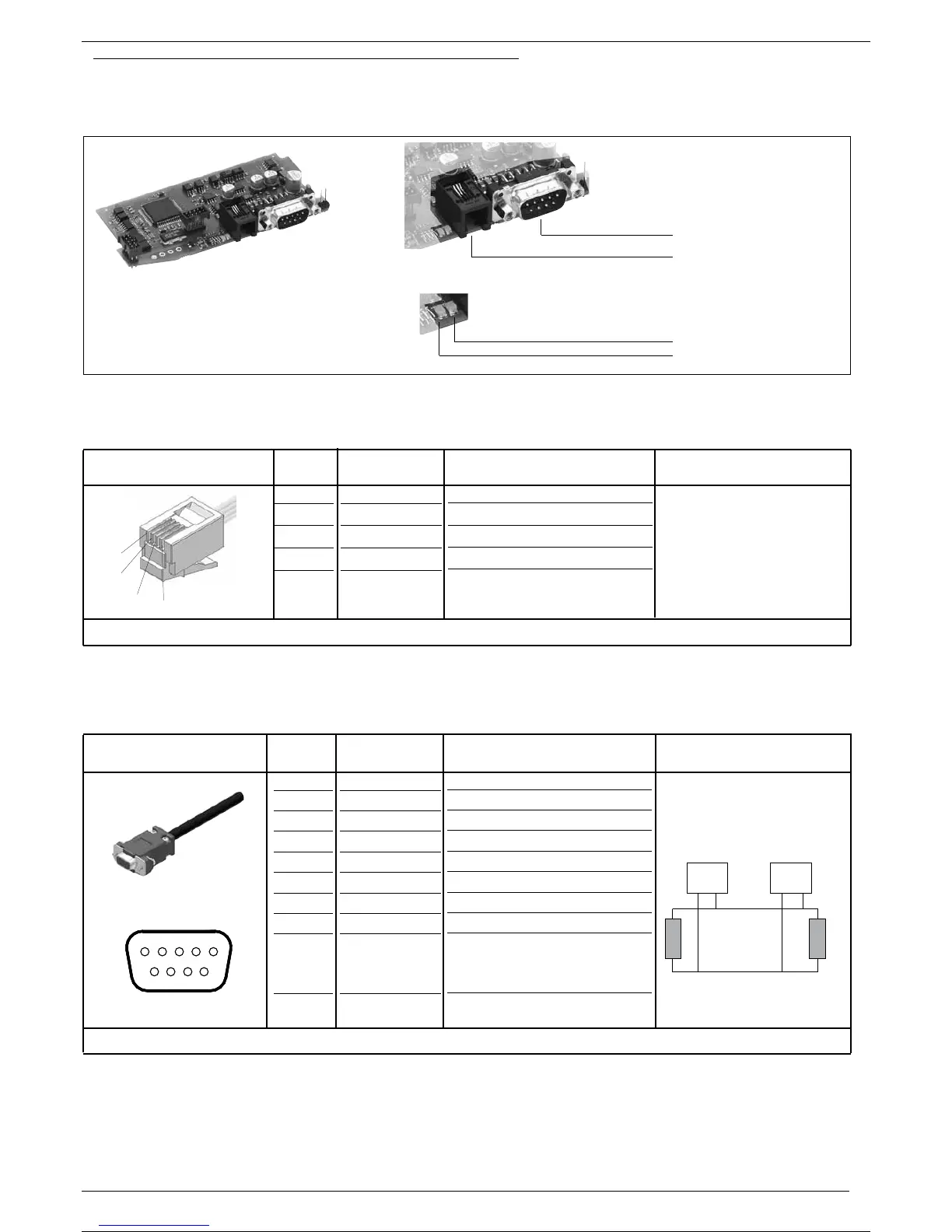
Port2 (fieldbus): connectors S4, S5 MODBUS RTU/CANopen
Figure 32 Port2: Fieldbus Modbus RTU/CANOpen Interface
Table 23
Table 24
4
3
2
1
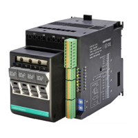
Cable type: flat telephone cable for fin 4-4 conductor 28AWG
Connector S4
RJ10 4-4 pin
Nr. Pin
Name
1
2
3
4
GND1 (**)
Rx/Tx+
Rx/Tx-
+V (reserved)
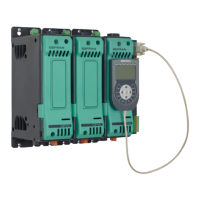
Cable type: Shielded 2 pairs 22/24AWG conforming to CANopen.
Connector S5
D-SUB 9 pins female
Nr. Pin Name
1
2
3
4
5
6
7
8
9
-
CAN_L
CAN_GND
-
(CAN_SHLD)
(GND)
CAN_H
-
(CAN_V+)
Description
-
Data reception/transmission (A+)
Data reception/transmission (B-)
-
Description
Reserved
CAN_L bus line (domination low)
CAN Ground
Reserved
Optional CAN Shield
Optional Ground
CAN_H bus line (domination high)
Reserved
Optional CAN external positive supply
(dedicated for supply of transceiver
and optocouplers, if galvanic isolation
of the bus node applies)
5 4 3 2 1
9 8 7 6
. . . . . . . .node 1 node n
CAN_L
CAN_H
CAN Bus Line
120 �
120 �
Connect the terminal resistances
as shown in the figure.
Note
Note
(**) Connect the GND signal
among Modbus devices with a line
distance > 100 m.
S4 female connector
S5 male connector
Red Led
Green Led
22 / 35