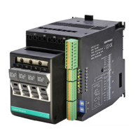
Port1 (local bus): Modbus serial interface – connectors S1, S2, S3
Figure 29
Connector S3 to connection at GFX-OP terminal or to Geflex slave modules (GFX-S1, GFX-S2)
Port 1
Port 2
S1
S2
S3
S4
S5
4
3
2
1
4
3
2
1
+VI
Tx/Rx-
Tx/Rx+
GNDI
+VI
Tx/Rx-
Tx/Rx+
GNDI
Table 19
4
3
2
1
Cable type: flat telephone cable for pin 4-4 conductor 28AWG
Connector S1/S2
RJ10 4-4 pin
Nr. Pin
Name
1
2
3
4
GND1 (**)
Tx/Rx+
Tx/Rx-
+V (reserved)
Description
-
Data reception/transmission (A+)
Data reception/transmission (B-)
-
Note
(*) Insert the RS485 line
termination in the last device
on the Modbus line, see dip-
switches.
(**) Connect the GND signal
among Modbus devices with a
line distance > 100 m.
19 / 35