2. Italiano
2.1. Protocollo di comunicazione MODBUS
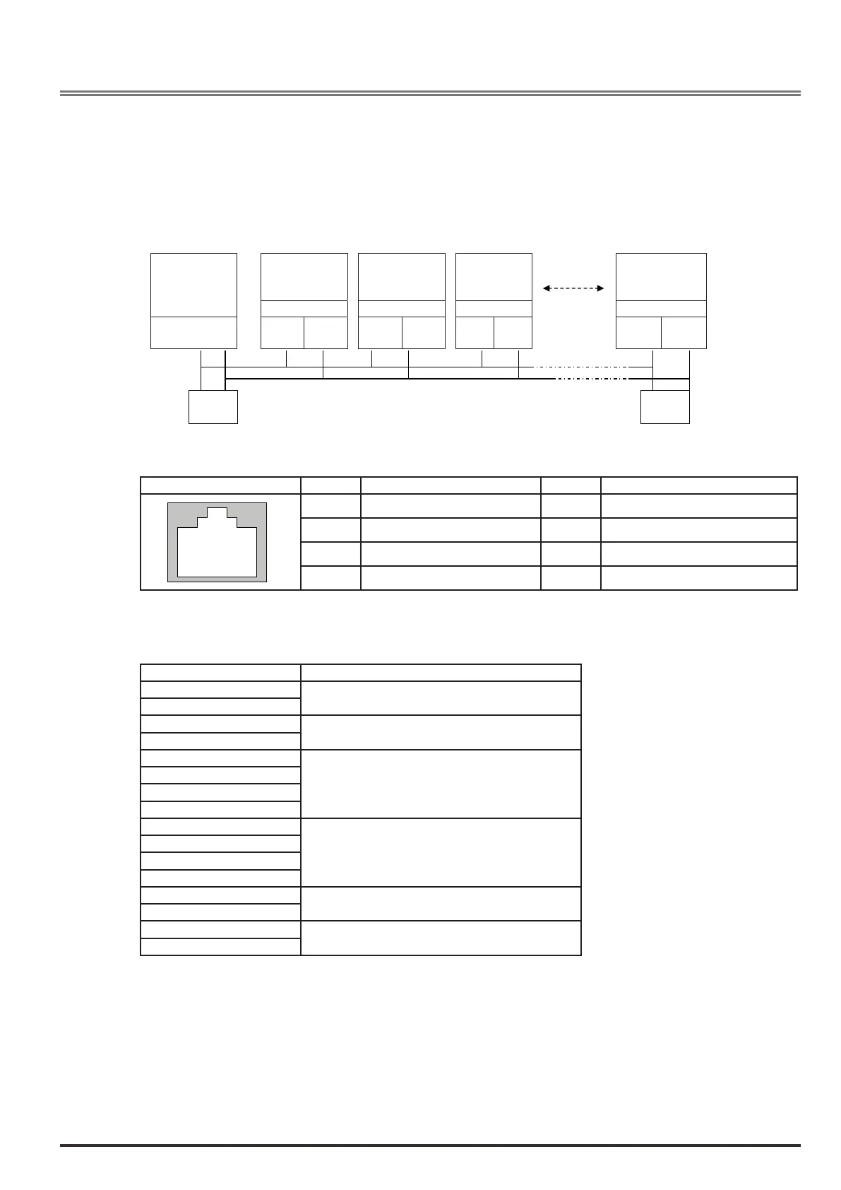
2.1.1. Communication Connection and Data Frame
La comunicazione di VDI100 può essere controllata mediante PC o altri regolatori, tramite RS485 o RS232,
con il protocollo Modbus in modalità RTU e il protocollo Modbus in modalità ASCII e la lunghezza del frame
massima è di 80 byte.
Installazione hardware
Controller
(PLC / HMI or
PC)
VDI100
Node
Address 01
VDI100
Node
Address 02
VDI100
Node
Address 03
VDI100
Node
Address FE
6NC 6NC 6NC 6NC
RS-485
Interface
S(+) S(-) S(+) S(-) S(+) S(-) S(+) S(-)
120Ω
1/4w
120Ω
1/4w
**Collegarelaresistenzaditerminazione(120Ω,1/4W)frailprimoel’ultimodispositivo.
CN6 Pin out PIN Segnale PIN Segnale
876 5 4321
1 Segnale RS-485 S+ 5 Segnale Tx
2 Segnale RS-485 S- 6 Segnale RS-485 S-
3 Segnale RS-485 S+ 7 VCC dell'alimentazione 5V isolata
4 Segnale Rx 8 GND dell'alimentazione 5V isolata
Per la comunicazione RS-485, utilizzare il pin1 o il pin 3 per S(+) e il pin 2 o il pin 6 per S(-)
Formato Data Frame
STX(3AH) Start Bit = 3AH
Node Address Hi
Communication Address (Station):
2-digit ASCII Code
Node Address Lo
Function Hi
Function Code (command):
2-digit ASCII Code
Function Lo
Command Start Address
Command Start byte:
4-digit ASCII Code
Command Start Address
Command Start Address
Command Start Address
Data length
The length of the command:
4-digit ASCII Code
Data length
Data length
Data length
LRC Check Hi
LRC Check Code:
2-digit ASCII Code
LRC Check Lo
END Hi
End Byte:
END Hi=CR(0DH), END Li = LF(0AH)
END Lo
VDI100 • Instruction manual 21

 Loading...
