www.gemu-group.com62 / 76GEMÜ 1436 cPos
16 Operation
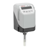
16.2.3.8.1.2 Defining the characteristics of the control curve
W-Function:
The characteristics of the control characteristic can be
defined (linear/ 1:25 / 1:50 / free).
0,0
20,0
40,0
60,0
80,0
100,0
120,0
0 20 40 60 80 100 120
In order to be able to close the valve fully at a characteristic
selection of 1:25 or 1:50, the close tight function must be set
to the value >2.0 (for characteristic 1:50) or >4.0 (for charac-
teristic 1:25).
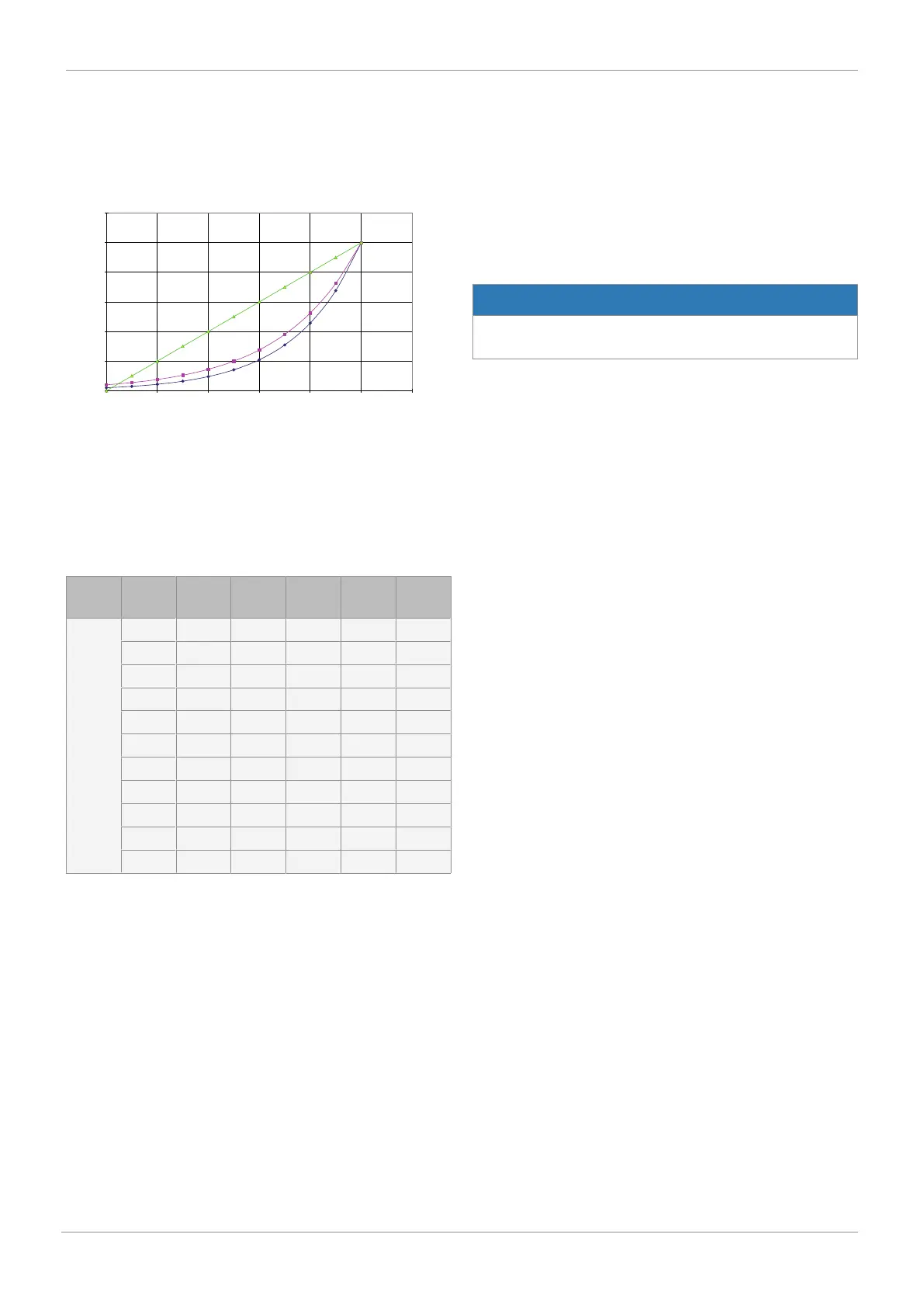
SetW-free:
Eleven calibration points on the control characteristic can be
programmed as required.
Display Func-
tion
P1 P2 P3 P4 Default
setting
Set W-
free
0 % 0 %
10 % 10 %
20 % 20 %
30 % 30 %
40 % 40 %
50 % 50 %
60 % 60 %
70 % 70 %
80 % 80 %
90 % 90 %
100 % 100 %
Y-Direction:
Defines the direction of the process controller output (rising /
falling). An inverted process control system can be realized.
16.2.3.8.1.3 Defining the direction of the travel sensor
Pot Dir:
The direction of the actual value potentiometer can be
defined.
Rise: For valves with rising direction of action
- Linear actuators: Valve spindle rises when valve opens
- Quarter turn actuators: Viewed from above, shaft turns anti-
clockwise when valve opens.
Fall: For valves with falling direction of action
- Linear actuators: Valve spindle falls when valve opens
- Quarter turn actuators: Viewed from above, shaft turns
clockwise when valve opens.
In combination with the respective direction of the valve,
these settings mean that the valve opens when the signal
rises and the display and output values have the same direc-
tion of action. If valves are operated in reverse (rising signal
closes valve), the W-Direction parameter must be reset, other-
wise the display and the output signal would be inversed.
16.2.3.8.1.4 Defining the actual value output signal
NOTICE
▶ If a higher value is entered for OutMinPos than for Out-
MaxPos, the direction of the output signal is inverted.
OutMinPos:
Defines the valve position at which an actual value signal of 4
mA is emitted at the output.
OutMaxPos:
Defines the valve position at which an actual value signal of
20 mA is emitted at the output.
16.2.3.8.1.5 Determining switch points for error monitoring
I Min W:
Defines the point below which the set value signal activates
an error message.
I Max W:
Defines the point above which the set value signal activates
an error message.
I Min X:
Defines the point below which the actual value signal activ-
ates an error message.
I Max X:
Defines the point above which the actual value signal activ-
ates an error message.
16.2.3.8.1.6 Scaling the actual value and set value display
Scaling:
Submenu for scaling the actual value and set value display,
which defines whether the actual value and set value display
is to be displayed as a scaled variable or in percent.
ON: display as scaled variable; OFF: display in percent
This setting point can be used to adapt the display to the
physical variable of the controlled system to be regulated.
This means that the variable to be regulated can be entered
and read directly.
With the control of process variables (ProcCtrl Mode: ON), the
setting must correspond to the signal output of the process
sensor.
The physical unit is entered separately from the value in the
same context.
Typical setting values:
- xx °C / °F → temperature control
- xx bar / psi → pressure control
- xx l/h / m³/h → flow control
 Loading...