EasyManua.ls Logo

GEM 600 User Manual

GEM 600
19 pages
To Next Page IconTo Next Page
Page #1 background imageLoading...
Page #1 background image
600, 630
600, 630
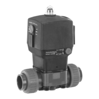
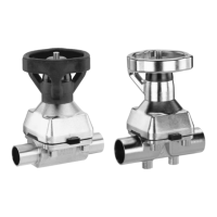
Diaphragm Valve
Plastic, DN 12 - 50
INSTALLATION, OPERATING AND
MAINTENANCE INSTRUCTIONS
Actuator size Code 1
GB
Actuator size Code 2-4
Membranventil
Kunststo , DN 12 - 50
DE
ORIGINAL EINBAU- UND MONTAGEANLEITUNG
GEMÜ 600
Antriebsgröße Code 2-4
GEMÜ 630
Antriebsgröße Code 2-4
GEMÜ 630
Antriebsgröße Code 1

Questions and Answers:

GEM 600 Specifications

General IconGeneral
BrandGEM
Model600
CategoryControl Unit
LanguageEnglish

Summary

General safety information

Service and operating personnel safety

Fundamental safety information for commissioning, operation, and servicing personnel.

Warning notes and signal words

Explanation of signal words and danger levels used for warnings.

Definition of terms

Working medium definition

The medium that flows through the diaphragm valve.

Control medium definition

Medium used to actuate and operate the valve.

Control function definition

Possible actuation functions of the diaphragm valve.

Intended area of use

Condition as supplied to customer

Technical data

Order data

Manufacturer's information

Transport and handling guidelines

Guidelines for safe and careful transportation and handling of the diaphragm valve.

Delivery and storage instructions

Instructions for checking parts upon receipt and recommended storage conditions.

Required tools

Information on tools needed for installation and assembly, not included in scope.

Functional description

Construction overview

Installation and connection

Pre-installation checks and preparation

Checks and preparations required before installing the diaphragm valve.

Valve installation methods

Covers various methods for installing the diaphragm valve, including spigot, union, threaded, and flange types.

Control functions and operation

Explanation of control functions, connecting control medium, and optical indicators.

Stroke limiter and manual override

Procedures for setting the stroke limiter and operating the manual override.

Assembly and disassembly

Valve disassembly (removing actuator)

Steps to separate the actuator from the valve body.

Diaphragm removal and mounting

Procedures for removing and correctly mounting the diaphragm.

Diaphragm mounting general information

Key principles and checks for mounting the correct diaphragm.

Mounting concave diaphragm

Mounting convex diaphragm

Actuator mounting on valve body

Commissioning

Inspection and servicing

Disassembly procedures

Disposal guidelines

Returns process

Information and staff training

Troubleshooting and fault clearance

Sectional drawings and spare parts

Related product manuals