28 / 44
600, 630
2
A
1
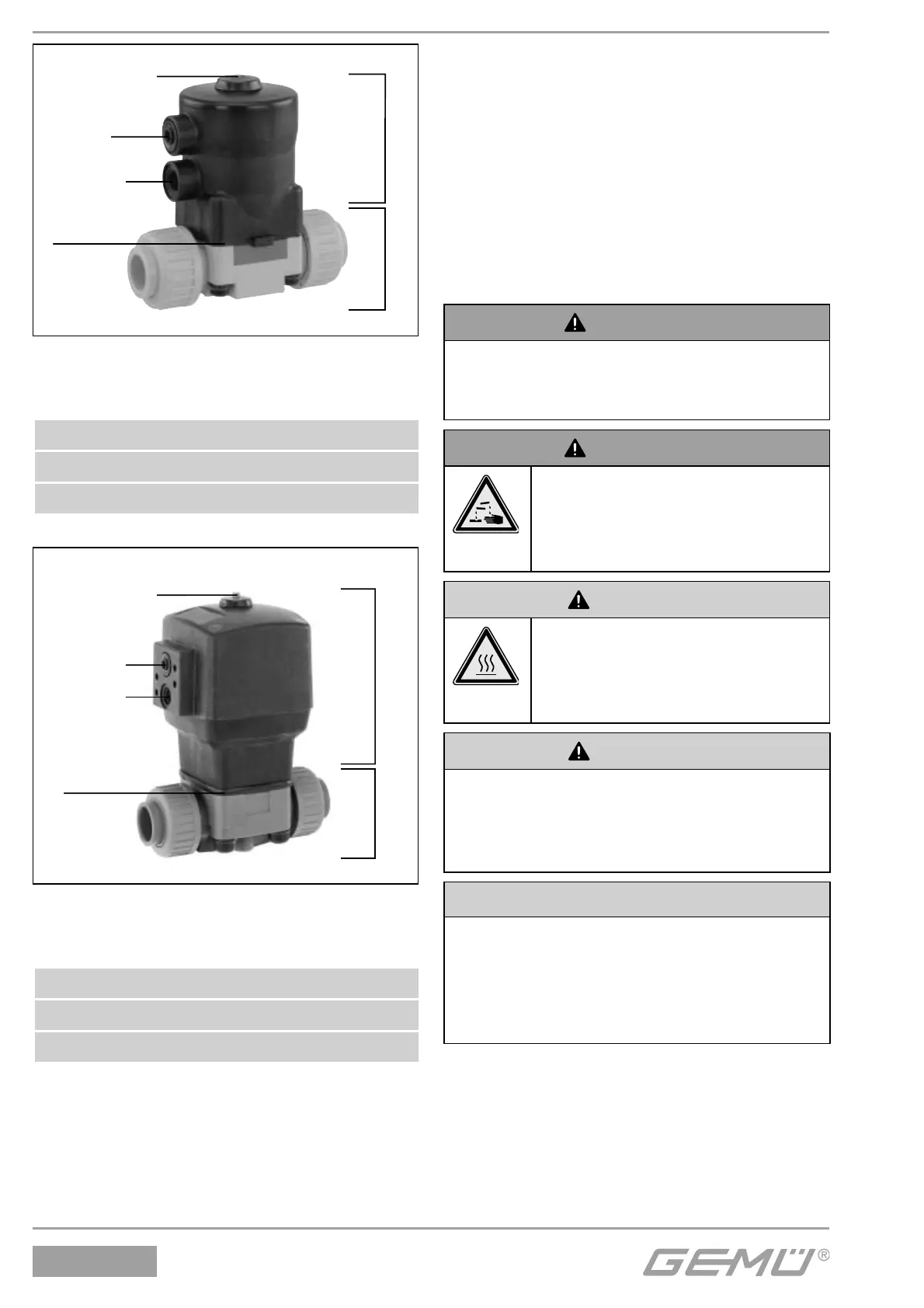
Optical position
indicator
Vent hole
Connector 2
Construction - GEMÜ 630
Actuator size Code 1
A Actuator
1 Valve body
2 Diaphragm
2
A
1
Optical position
indicator
Connector 4
Connector 2
Construction - GEMÜ 630
Actuator size Code 2-4
A Actuator
1 Valve body
2 Diaphragm
11 Installation and connection
Prior to installation:
G
Ensure that valve body and diaphragm
material are appropriate and compatible
to handle the working medium.
G
Check the suitability prior to the
installation.
See chapter 6 "Technical data".
11.1 Installing the diaphragm valve
WARNING
The equipment is subject to pressure!
® Risk of severe injury or death!
G
Only work on depressurized plant.
WARNING
Corrosive chemicals!
®
Risk of caustic burns!
G
Wear appropriate protective
gear when installing.
CAUTION
Hot plant components!
®
Risk of burns!
G
Only work on plant that has
cooled down.
CAUTION
Never use the valve as a step or an aid
for climbing!
®
This entails the risk of slipping-off or
damaging the valve.
CAUTION
Do not exceed the maximum
permissible pressure!
® Take precautionary measures to
avoid possible pressure surges
(water hammer).
G
Installation work must only be performed
by trained personnel.
G
Use appropriate protective gear as
specifi ed in plant operator's guidelines.