653, 654
16 / 28
Important:
If the diaphragm is not screwed
into the adapter far enough, the
closing force is transmitted directly
onto the diaphragm pin and not
via the compressor. This will cause
damage and early failure of the
diaphragm and thus leakage of the
valve. If the diaphragm is screwed
in too far no perfect sealing at the
valve seat will be achieved. The
function of the valve is no longer
ensured.
Important:
Incorrectly mounted diaphragm
may cause valve leakage /
emission of medium. In this case
remove the diaphragm, check the
complete valve and diaphragm and
reassemble again proceeding as
described above.
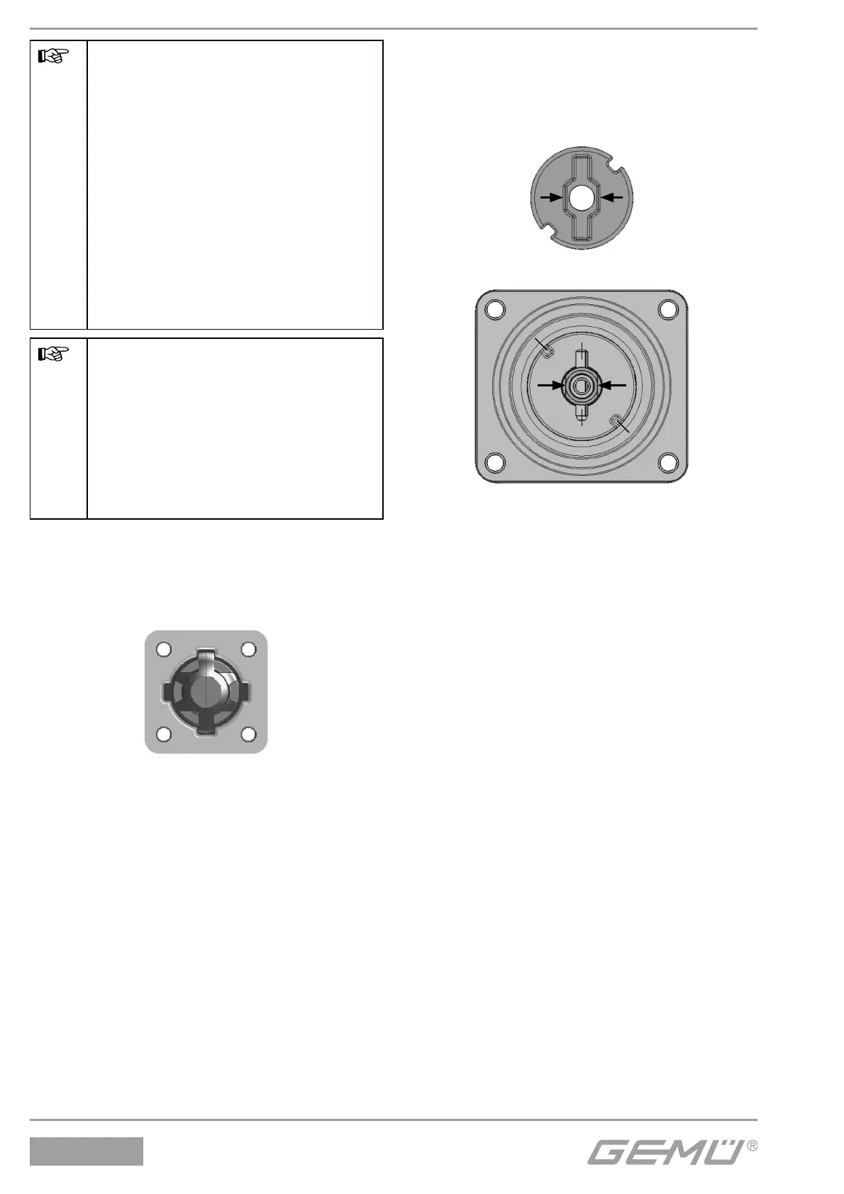
Diaphragm size 8:
The compressor is fixed to the spindle.
Compressor and bonnet flange seen from
below:
Diaphragm size 10:
The compressor is loose.
Compressor and bonnet flange seen from
below:
B
D
C
D
B
C
A
A
Pict. 1
Pict. 2
Anti-twist system of the spindle at the
compressor
A double flat (arrows picture 1) is fitted at
the end of the bonnet spindle to protect the
spindle against twisting. When mounting
the compressor, the double flat must be
in correct alignment with the recess of the
compressor back (arrows picture 2).
If the bonnet spindle is not in the correct
position, it must be turned to the correct
position. The position of A is offset by 45° to
the position of C.
Place the compressor loosely on the bonnet
spindle, fit the recesses D into the guides C
and A into B. The compressor must be able
to be moved freely between the guides!