23(5$7,21
59$5(*8/$72523(5$7,21237,21)257+(7+5
These units are used for multiple zone heating
networks featuring:
- a circulating pump,
- a mixer valve.
These units can communicate with each other as
well as with the RVA 47 and the LGMs and thus
form a complete heating system.
The control of the flow temperature of the heating
circuit with a mixer valve and/or a circulating pump
is carried out either:
- according to external conditions,
- according to external conditions with room in-
fluence.
A simple button is used to set the room temperature
comfort setting.
The RVA 46 regulator controls a pump circuit by de-
fault.
As soon as the heating flow temperature sensor
(QAD 21) is connected to the RVA 46, the RVA 46
automatically recognizes that the circuit is equipped
with a mixer valve.
&RQWURORIDSXPSFLUFXLWXVLQJDQ59$
1RIORZWHPSHUDWXUHVHQVRU4$'
LVFRQQHFWHGWRWKH59$
- With no QAA 70 room sensor on the pump cir-
cuit:
• the pump circuit flow temperature is defined by
the slope of the RVA 46 for a 20 °C room tem-
perature,
• corrections relating to this room temperature
are carried out by the room temperature con-
trol knob of the RVA 46 (item no. 1, fig. 19)
(setting from 8 to 26 °C).
- With a QAA 70 room sensor on the pump circuit:
• the room temperature control knob of the
RVA 46 (item no. 1, fig. 19) becomes inactive,
• the pump circuit room temperature setting is
set on the room sensor (setting value program-
med in line 1 of the room sensor + correction
with the control knob +/- 3 °C).
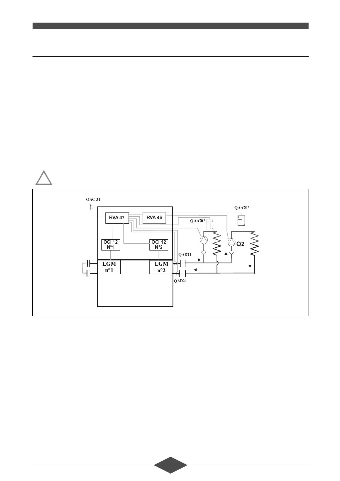
!
7+5
4$&
4$'
4$'
/*0
Q
/*0
Q
2&,
1
2&,
1
59$
4
4$$
59$
4$$
4
)LJ
 Loading...