&200,66,21,1*
&200,66,21,1*
Activate the boiler’s external electrical circuit-break-
er.
During initial commissioning, the heating engineer
must check:
- the correct operation of each module,
- the correct operation of RVA control.
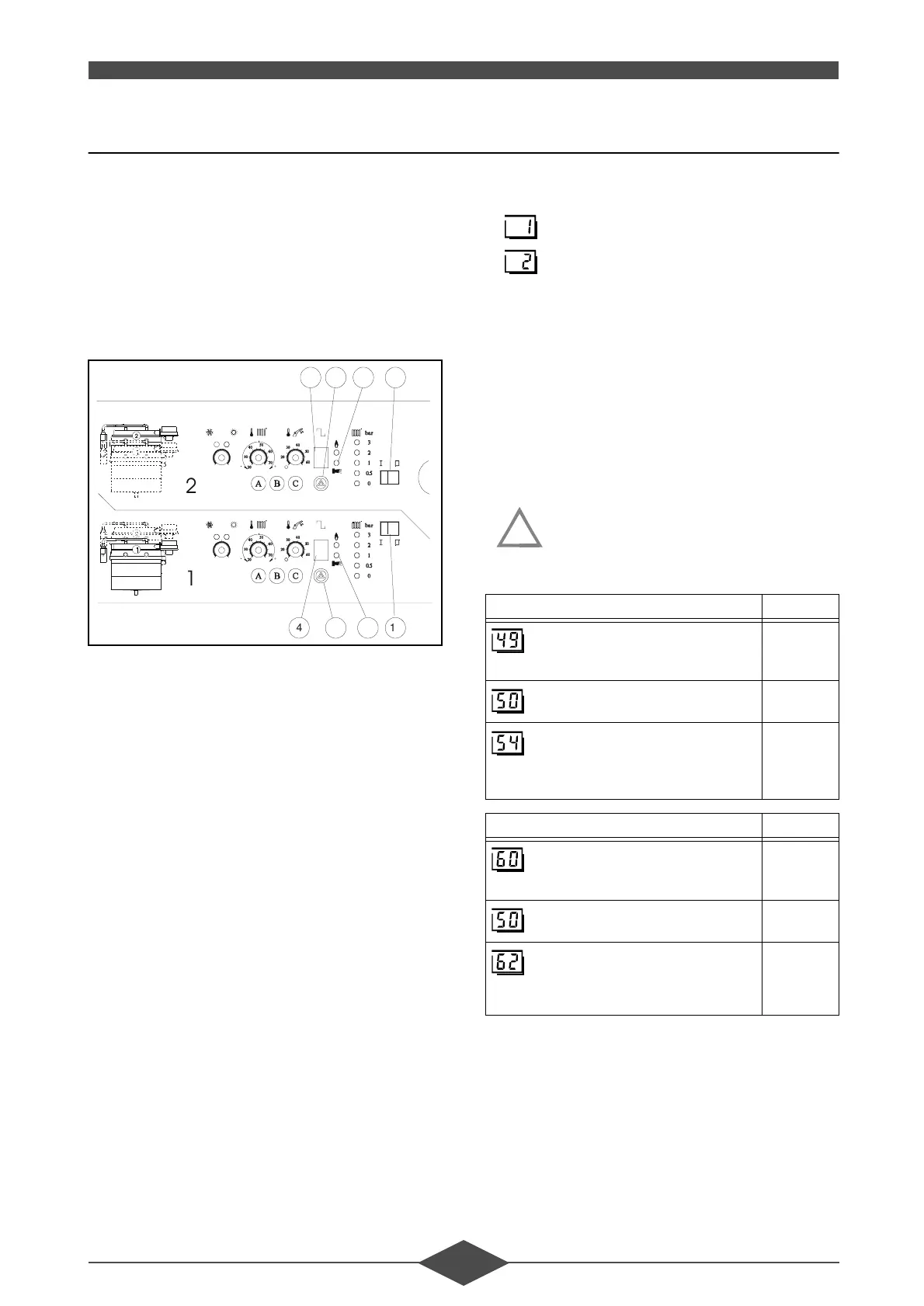
&RQWURORIHDFKPRGXOH¶VRSHUDWLRQ
- activate the On/Off switches (item no. 10) of each
module.
- an LGM self-regulation phase of each module be-
gins and signals /3& appear in succession
on the displays (item no. 4) then and finally 2.
Note:
- The alarm indicator (item no. 6) is on:
• manually reset button (item no 8),
• if the alarm continues, refer to the operating
fault list paragraph 1 - section XI - OPERA-
TING FAULTS.
- Check the setting of the burners. The burners are
preset for natural gas H (G20). However, during
commissioning, separate CO2/CO combustion
verifications must be carried out on each module
(paragraph 3 - section VII - COMBUSTION CON-
TROL).
&KHFNLQJ59$FRQWURO
3DUDPHWHUVHWWLQJ
- The basic THR 10-100 requires no specific pro-
gramming. The RVA 47 is preprogrammed.
- When the RVA 46 option is integrated into the
THR 10-100, the THR 10-100 requires program-
ming (paragraph 5 - section VIII - MULTICIRCUIT
WITH A THR 10-100),
- Set the time and day on regulator RVA 47:
(see paragraph 3.3 - section III - INSTALLATION
from the RVA 47 technical instructions)
: time setting,
: day setting.
Note:
- if one or several RVA 46s are connected to the
master RVA 47, their time and day are automati-
cally updated.
&RPPXQLFDWLRQFRQWURO
3DUDPHWHUFRQWURO
- Check that the following parameters do not indi-
cate any errors. If the displays differ from the dis-
plays in the following tables, see section XI -
OPERATING FAULTS.
)ROORZLQJ WKH HOLPLQDWLRQ RIWKHIDXOW
HUURUPHVVDJH(URQWKH59$PD\
WDNHWR PLQXWHVWRGLVDSSHDUDF
FRUGLQJWRWKHW\SHRIIDXOW
- Also check the location of the outside sensor and
if necessary test the inputs/outputs of each regu-
lator.
4 10
4 10
8 6
8 6
)LJ
59$5HJXODWRUSDUDPHWHUV 'LVSOD\
: display of BMU (LGM) error
codes
- - -
: error display
blank
: display of PPS communication
selection of PPS addresses using
buttons +/-
4 102
5 102
59$5HJXODWRUSDUDPHWHUV 'LVSOD\
: display of BMU (LGM) error
codes
blank
: error display
blank
:
display of PPS communication
if room sensor on RVA 46
- - -
or
1 83
!
 Loading...