&20%867,21&21752/
*$6)/2:&21752/&2&212;
7RFRQWUROWKHFRPEXVWLRQSDUDPHWHUV
PRUH HIIHFWLYHO\ WKH FRPEXVWLRQ RI
HDFKPRGXOHPXVWEHFRQWUROOHGRQH
PRGXOHRQWKHRWKHUPRGXOHRII
6XUYHLOODQFHSURFHGXUH
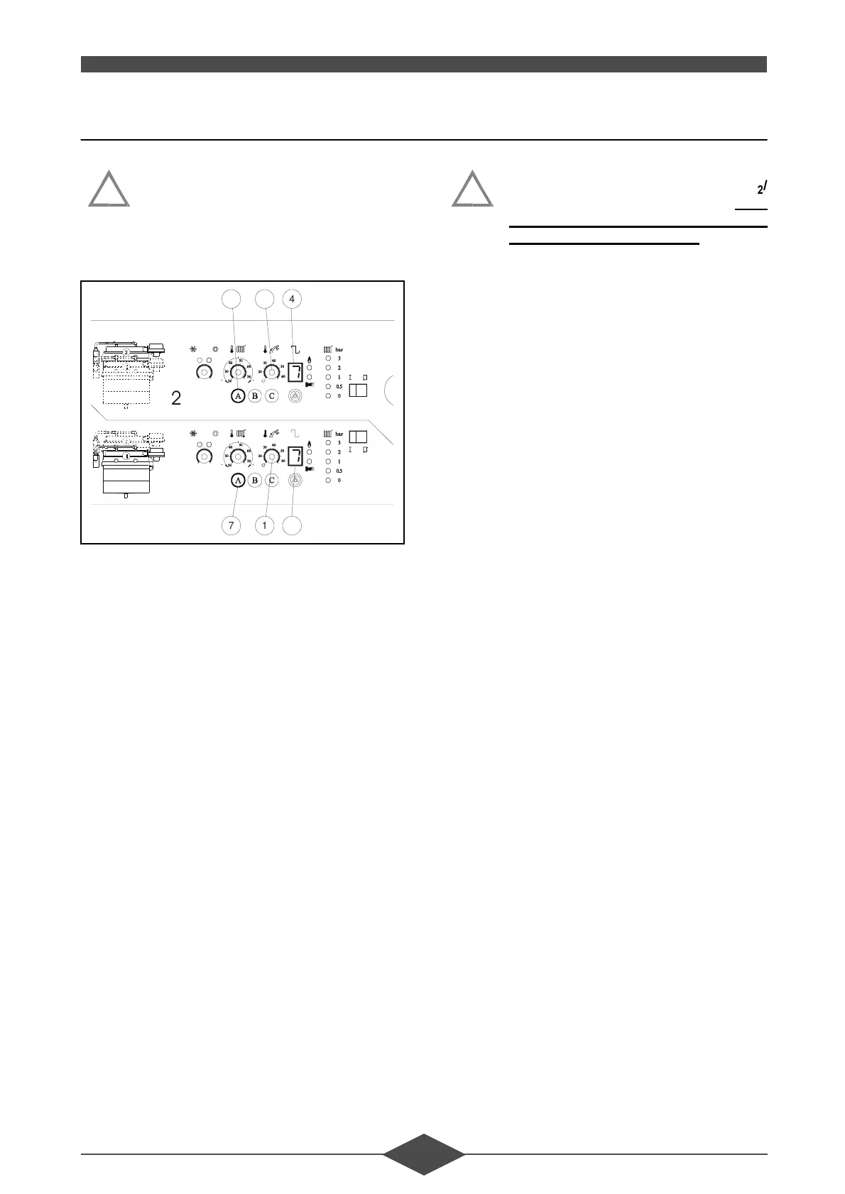
- To commission the burner:
• press button $ (item no. 7) on the LGM’s con-
trol panel for about 5 secs:
. flashing "" appears on the display (item
no. 4),
- progressively position the d.h.w. potentiometer
(item no. 1) to the maximum on the right:
• the burner switches to max. rate,
- check the CO
2
/CO ratio (see setting table para-
graph 3.2 - section VII - COMBUSTION CON-
TROL),
note:
The gas flow at maximum rate cannot be set, it is
set by the gas regulation plate.
- set the d.h.w. potentiometer (item no. 1) to the
maximum on the left:
• the burner switches to the minimum rate,
- Check the CO
2
/CO ratio (see setting table para-
graph 3.2 - section VII - COMBUSTION CON-
TROL),
- if necessary:
• adjust screw . (fig. 57) (screwing increases
gas flow and conversely).
%HIRUHVWDUWLQJWKHPLQLPXPUDWHVHW
WLQJVFUHZ. ZDLWIRUDVWDEOH&2
&2 DQDO\VHU UHDGRXW 5HSHDW VZLW
FKLQJ IURP WKH PLQLPXP UDWH WR WKH
PD[LPXPUDWHVHYHUDOWLPHVWRHQVXUH
WKDWWKHVHWWLQJKDVEHHQGRQHSURSHU
O\8VHDSUHFDOLEUDWHGDQDO\VHU
!
4
17 4
17
)LJ
!
 Loading...