%$6,&6(77,1*2)7+(7+5
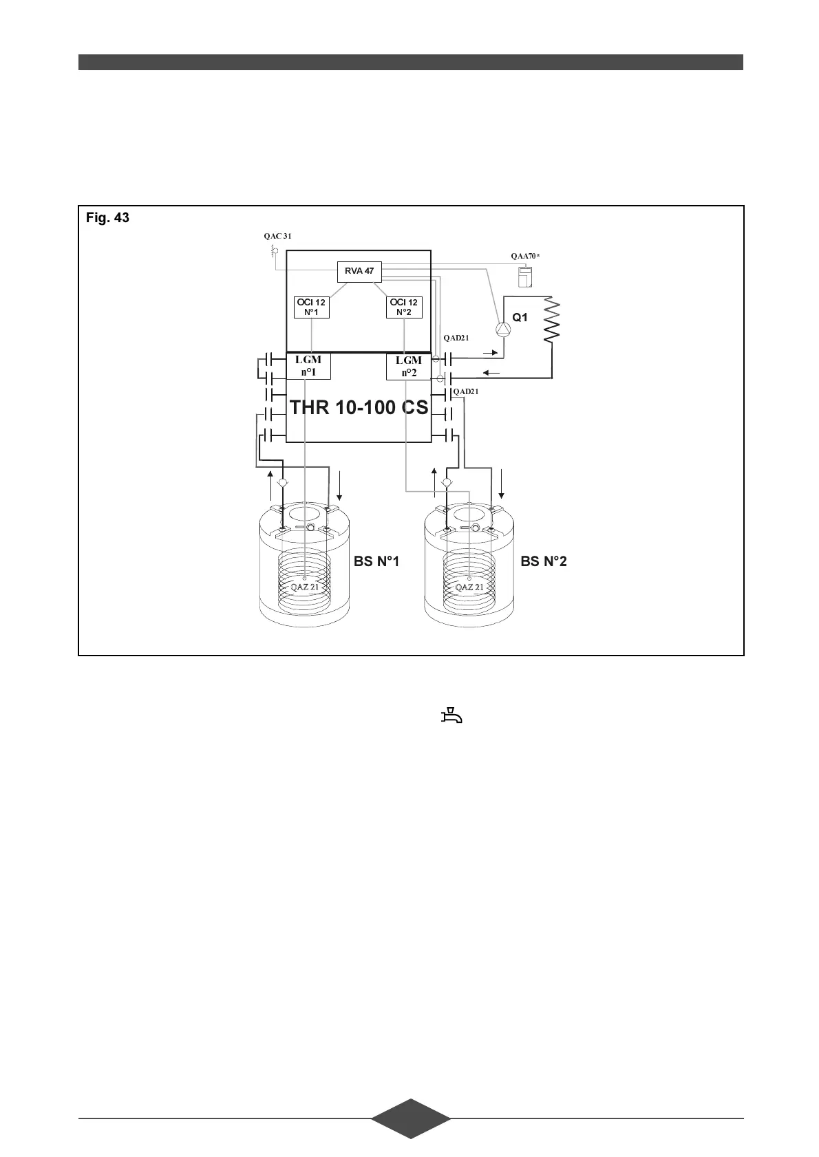
'KZ SURGXFWLRQ ZLWK D VHOHFWRU YDOYH YLD WZR /*0V WDQN FRQQHFWHG WR HDFK VHOHFWRU
YDOYH
The d.h.w. sensor of tank No.1 is connected to LGM
No.1 (Terminal ST 30).
The d.h.w. sensor of tank No.2 is connected to LGM
No.2 (Terminal ST 30).
%HQHILWV
- D.h.w. production with a selector valve,
- absolute d.h.w. priority,
- limited heat carriage: only the d.h.w. loops are at
a high temperature,
- it is possible to control a floor heating system di-
rectly via the pump circuit of the RVA 47 thanks
to the limited heat carriage.
'UDZEDFNV
- same d.h.w. setting for both tanks,
- same time programme for both tanks.
2SHUDWLRQDQGVHWWLQJ
The d.h.w. request must be communicated with the
button (d.h.w. on) on the RVA 47.
- the d.h.w. setting is set either
• in line 13 of the RVA 47,
• or in line 3 of QAA 70 of the RVA 47.
It is the same setting for both boilers.
- the d.h.w. setting potentiometers of the LGMs’
control panel are inactive,
- during a d.h.w. request, the relevant LGMs are in
d.h.w. mode (6 on the control panel display).
4$&
4$'
4$'
4$$
/*0
Q
/*0
Q
2&,
1
2&,
1
59$
4
7+5&6
%61%61
)LJ
 Loading...