08/7,&,5&8,7:,7+$7+5
$GGUHVVLQJ
67$1'$5',167$//$7,21
Standard installation makes possible:
- Domestic hot water production with a load pump
connected to the RVA 47,
- Or d.h.w. production with a selector valve control-
led by one of or the two BMUs of a
THR 10-100 CS.
- Control of a pump heating circuit by the RVA 47.
- Control of a pump circuit or of a circuit with a
mixer valve by the additional ZH 46 control
boxes.
Each RVA 46 zone regulator calculates a tempera-
ture setting according to the outdoor temperature,
the room temperature settings, the slopes or the
d.h.w. settings. The boiler temperature setting is the
highest temperature of all the zone regulator tempe-
rature settings.
In order to make parameter setting easier to unders-
tand, it is best to use a skeleton diagram. Thus the
diagrams of section III - OPERATION are fragmen-
ted (i.e. the RVA 46s are removed from the
THR 10-100).
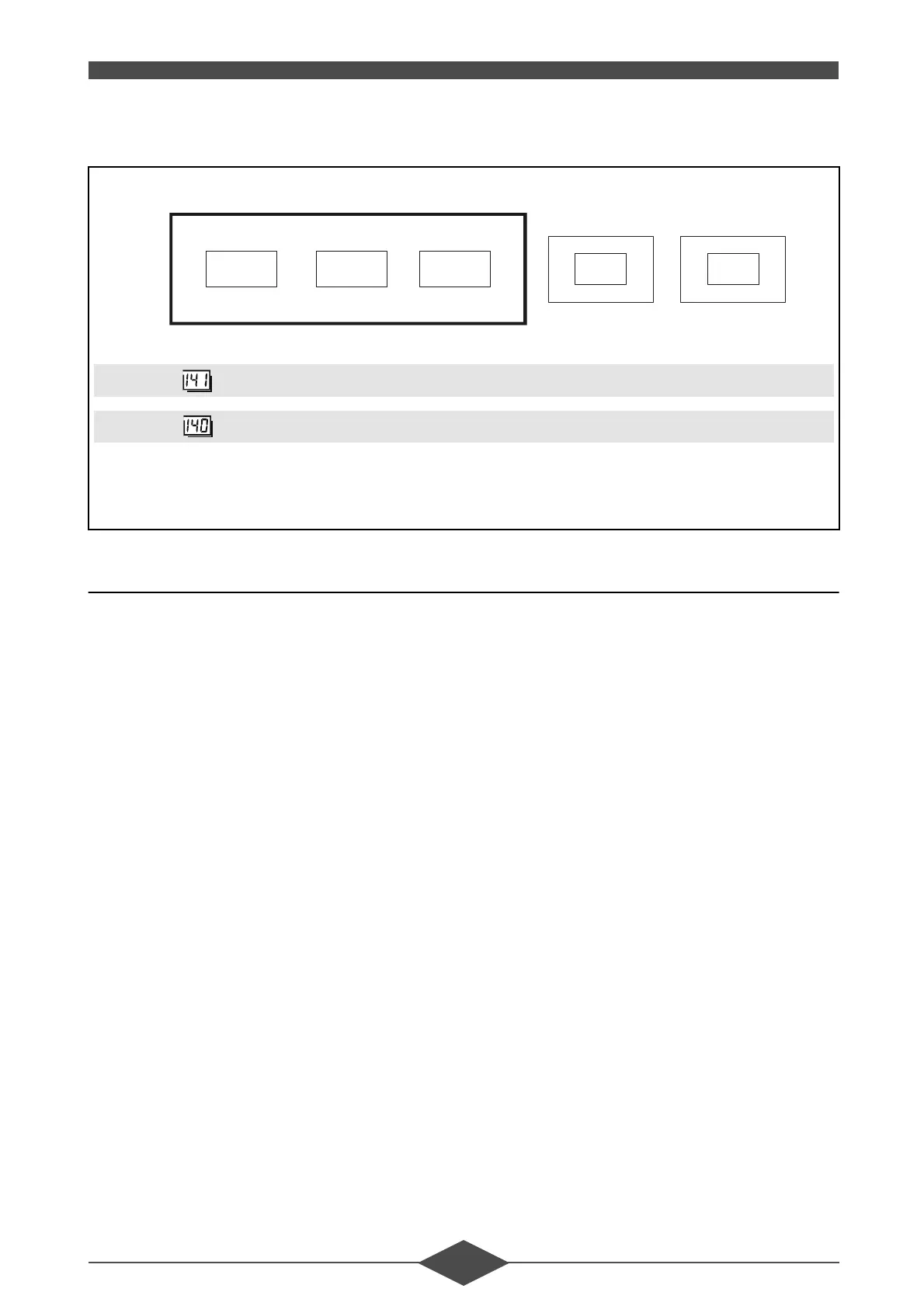
Unit
address
Segment
address
Segment 0 = Heat production unit RVA 47
⇒
Segment 1 = Heat distribution unit RVA 46
⇒
7+5
RVA 47 RVA 46 RVA 46
A
4
46
=+
011 1 1
112 3 4
)LJ
(see fig. 63 for complete parameter
setting)
 Loading...