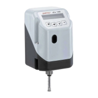
1436 cPos
®
10 / 24
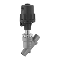
3 Pneumatic connections
G Make the connection between pneumatic
positioner outlet A1 (single acting) or
A1 and A2 (double acting) and the
pneumatic actuator air control inlet.
G Connect the control air supply (additional
air) to connection P* (max. 7 bar or
101 psi).
CAUTION
Observe maximum actuator control
pressure!
1
5
43
2
1
5
43
2
1
5
43
2
1
V2
3
V5
V1
V4
V3
2
4
Connection Description
1 Air supply connector P
3 Venting connection G1/8 with silencer
V1 Additional air throttle for A1
V2 Outgoing air throttle for A1
V3 Outgoing air throttle for A2
V4 Additional air throttle for A2
V5 Non-return valve
2 Working connection for process valve
c.f. 1 and 2 (A1)
4 Working connection for process valve
c.f. 3 (A2)
All pneumatic connectors are G1/8
4 Electrical connections
CAUTION
G Connect analogue input (set value
input) 0/4-20 mA to plug X3.
G Connect supply voltage 24 V DC to
plug X1.
G If operating as a process controller,
connect analogue input (actual
value input) 0/4-20 mA to plug X3.
CAUTION
Danger of cable break!
® Damage to the device.
● Turn electrical connections
max. 360°.
1
4
3
2
5
max. 360°
4.1 Standard
X1 X3
X2
1
5
43
2
1
5
43
2
1
5
43
2
Connection Pin Signal name
X1
M12 plug
A coding
1 Uv, 24 V DC supply voltage
2
Switching output K1, 24 V DC
(switches Uv*)
3
GND, (supply voltage,
DigIn1+2+W+X; K1+2)
4
Switching output K2, 24 V DC
(switches Uv*)
5 Digital input 1 (optional**)
Connection Pin Signal name
X2
M12 plug
B coding
1 I+, actual value output
2 I-, actual value output
3 RxD, Receive Data, RS232
4 TxD, Transmit Data, RS232
5 GND, RS232
4-20 mA
internal sup-
ply; active
}
Connection Pin Signal name
X3
M12 plug
A coding
1 W+, set value input
2 W-, set value input / Digital In W**
3
X+, process actual
value input
4
X-, process actual value input /
Digital In X**
5 Digital input 2 (optional**)
Working as
a process
controller
}
 Loading...