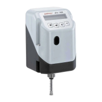
1436 cPos
®
9 / 24
2.2.3 Mounting the positioner
G Place the adapter 4 on the shaft of the
travel sensor.
G Place the positioner with the travel sensor
and mounting bracket onto the actuator.
G The adapter lug 5 must engage in the
actuator shaft groove.
G Attach the mounting bracket 1 to the
actuator with the enclosed screws.
View X
1
4
5
90°
45°0°
View X with adapter
3
View X only travel sensor
2
Travel sensor with marking
2.2.4 Checking the mounted assembly
G Connect the positioner to power and air
supply.
G The following message is displayed:
NoInit XX.X%
The mounted actuator can be moved to the
OPEN and CLOSED positions using the +
and - keys.
The displayed valve position must be
between 0 % and 100 %.
If the displayed valve position is not within
the range of 0 % and 100 %, the mechanical
mounting must be checked again.
2.3 Remote mounting to linear or
quarter turn actuators
2.3.1 Preparation of the valve actuator
See chapter 2.1.1 or 2.2.1.
2.3.2 Assembling the travel sensor
See chapter 2.1.2 or 2.2.2.
2.3.3 Checking the mounted assembly
See chapter 2.2.4.
2.3.4 Mounting the mounting bracket
G Push the positioner connection adapter
through the hole in the mounting bracket
and attach it with the enclosed nut.
G Use the bolt holes and appropriate fi xings
to attach the mounting bracket securely.
CAUTION
Ensure adequate stability of the base
used for attachment.
The positioner must be protected
against mechanical stress by the
operator.
Do not use the positioner as a climbing
support.
2.3.5 Connecting the travel sensor
The 5-pin M12 travel sensor plug must
be connected to the 5-pin M12 positioner
socket.
 Loading...