Do you have a question about the Gemu 1436 cPos and is the answer not in the manual?
Steps for initialising the positioner automatically.
Describes the steps for initialising the positioner automatically.
Details safety precautions for installation, operation, and qualified personnel.
Procedures to verify correct mechanical installation and sensor alignment.
Instructions for connecting power supply and input signals.
Procedures for commissioning when the positioner is not pre-mounted.
Steps for automatic adaptation of the positioner to the valve.
Steps for manual adaptation, used when automatic fails or for fine-tuning.
Flowchart detailing the steps for automatic and manual initialisation.
Instructions for initial setup when the positioner is pre-mounted.
Details the normal operating mode where the positioner responds to set values.
Explains manual valve control or set value adjustment.
Parameters related to valve initialisation.
Parameters for adjusting positioner behavior.
Configuration of digital outputs K1/K2, including switch points and functions.
Procedure for managing password protection and user access levels.
How to view, clear, and manage error and warning messages.
Explanation of starting automatic or manual positioner initialisation.
Configuration of PID control parameters for process control applications.
Configures the relationship between set value and valve position.
Quick steps to modify input signal settings.
Simple procedure to enable or disable the process controller function.
Adjusts the proportional gain (Kp) of the process controller.
Sets the integral reset time (Tn) for the process controller.
Table entries for SetCalibration parameters.
| Brand | Gemu |
|---|---|
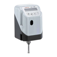
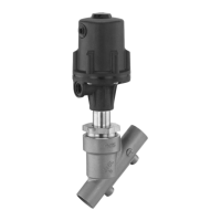
| Model | 1436 cPos |
| Category | Valve Positioners |
| Language | English |