7 / 66
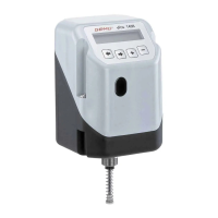
1436 cPos
4 Mechanical mounting
4.1 Mounting to linear actuators
4.1.1 Preparation of the valve actuator
1. The actuator must be in the zero position (actuator vented).
2. Should there be an optical position indicator in the actuator
(a red spindle), it must be removed.
4.1.2 Assembling the travel sensor
DANGER
Pretensioned spring!
P Damage to the device.
● Slowly relax spring.
Attention: Damage to the spindle surface may lead
to failure of the travel sensor!
The travel sensor is assembled using a mounting kit
1436S01Z... (direct mounting) or 4232S01Z... (remote
mounting) consisting of a spring, an operating bush and a
threaded adapter (if applicable).
The mounting kit depends on the valve type.
Travel sensor
Spindle
Spring
Operating bush
Mounting kit
1. Pull out the spindle of the travel sensor up to the limit stop.
2. Push the spring over the spindle.
3. Fix the spindle at point a
(thespindlemustnotbedamagedduringthis
process).
a
4. Screw the operating bush onto the spindle.
4.1.3 Mounting the positioner
1
2
3
● Mount the positioner 1 by screwing the travel sensor
hexagonal nut SW27 2 into the actuator 3.
The positioner must not be xed by turning
the housing as this may result in the danger of
overturning the internal stop.
If correctly mounted to the valve, the positioner can be turned
370°.
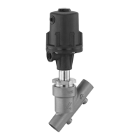
4.1.4 Mounting the external travel sensor
(onlyforversionwithremotemounting)
5
3
1
Valve with external travel sensor
1. Fit positioner 1 somewhere suitable.
The GEMÜ 1446 00 ZMP mounting bracket (to
be ordered separately) can be used to accom-
plish this.
2. Assemble the travel sensor (see chapter 4.1.2 "Assembling
the travel sensor").
3. Place travel sensor 5 on actuator 3 and attach travel
sensor 5 using a suitable open-end wrench SW27.
SW27
3
5
Travel sensor and actuator
Travel sensor mounted on actuator