10 / 66
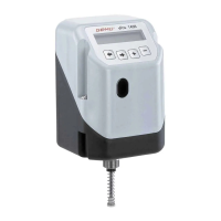
1436 cPos
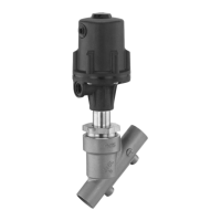
4.3 Remote mounting to linear or quarter turn
actuators
4.3.1 Preparation of the valve actuator
See chapter 4.1.1. or 4.2.1.
4.3.2 Assembling the travel sensor
See chapter 4.1.2. or 4.2.2.
4.3.3 Mounting the external travel sensor
(onlyforversionwithremotemounting)
See chapter 4.1.4. or 4.2.4.
4.3.4 Checking the mounted assembly
See chapter 4.2.5.
4.3.5 Mounting the mounting bracket
w Ensure adequate stability of the base used for
attachment.
w The positioner must be protected against
mechanical stress by the operator.
w Do not use the positioner as a climbing support.
1. Push the positioner connection adapter through the hole in
the mounting bracket and attach it with the enclosed nut.
2. Use the bolt holes and appropriate xings to attach the
mounting bracket securely.
4.3.6 Connecting the travel sensor
The 5-pin M12 travel sensor plug must be connected to the
5-pin M12 positioner socket.
5 Pneumatic connections
Attention: Observe maximum actuator control
pressure!
1. Make the connection between pneumatic positioner outlet
A1 (single acting) or A1 and A2 (double acting) and the
pneumatic actuator air control inlet .
2. Connect the control air supply (additional air) to the air
supply connection P 1 (max. 7 bar or 101 psi).
1
5
43
2
1
5
43
2
1
5
43
2
1
V2
3
V5
V1
V4
V3
2
4
Connection
DINISO
1219-1
Description Size
P 1 Air supply connection G1/8
R 3 Venting connection with silencer G1/8
V1 V1
Additional air throttle for A1
(connector 2)
-
V2 V2
Exhaust air throttle for A1
(connector 2)
-
V3 V3
Exhaust air throttle for A2*
(connector 4)
-
V4 V4
Additional air throttle for A2*
(connector 4)
-
V5 V5 Check valve -
A1 2
Working connection for process valve
(control function 1 and 2)
G1/8
A2 4
Working connection for process valve
(control function 3)
G1/8
* only double acting type (code 3)
6 Electrical connections
Danger of cable break!
P Damage to the device.
● Turn electrical connections
max. 360°.
1
4
3
2
5
max. 360°
To ensure safe restarting of the positioner following
interruption of the power supply, the power
interruption must be longer than 3 seconds.
1. Connect 24V DC supply voltage to plug X1.
2. Connect analogue input (set value input) 0/4-20 mA to plug
X3.
3. If operating as a process controller, connect analogue input
(actual value input) 0/4-20 mA to plug X3.