11 / 66
1436 cPos
X1 X3
X2
1
5
43
2
1
5
43
2
1
5
43
2
Connection Pin Signalname
X1
M12 plug
A coding
1 Uv, 24 V DC supply voltage
2 Switching output K1, 24 V DC (switches Uv*)
3 GND, (supply voltage, DigIn1+2+W+X; K1+2)
4 Switching output K2, 24 V DC (switches Uv*)
5 Digital input 1 (optional**)
Connection Pin Signalname
X2
M12 plug
B coding
1 I+, actual value output
2 I-, actual value output
3 RxD, Receive Data, RS232
4 TxD, Transmit Data, RS232
5 GND, RS232
4-20 mA internal
supply; active
}
Connection Pin Signalname
X3
M12 plug
A coding
1 W+, set value input
2 W-, set value input / Digital In W**
3 X+, process actual value input
4
X-, process actual value input /
Digital In X**
5 Digital input 2 (optional**)
Working as
a process
controller
}
* Switching output switches device supply voltage Uv - drop voltage
** For options code 01
6.1 Version with external actual value
potentiometer(codeS01)
X4
1
5
4
3
2
X4
Connection Pin Signalname
X4
M12 socket
A coding
1 UP+, output potentiometer supply voltage (+)
2 UP, input potentiometer wiper voltage
3 UP-, output potentiometer supply voltage (-)
4 n.c.
5 n.c.
6.2 Supplyvoltage
Plug Pin Signalname Wiring
X1 1 24 V DC supply voltage
internal
24 V DC
power
supply
external
-
+
X1 3 GND
6.3 Setvalueinput
(onlyeectiveforAUTOoperatingmode)
Plug Pin Signalname Wiring
X3 1 I+, set value input
internal
0/4 - 20 mA
external
-
+
GND
X3 2 I-, set value input
6.4 Actual value input
(sensorsignalwhenoperatingasaprocess
controller)
Plug Pin Signalname Wiring
X3 3 I+, actual value input
internal
0/4 - 20 mA
external
-
+
GND
X3 4 I-, actual value input
6.5 Actual value output
Plug Pin Signalname Wiring
X2 1
I+, actual value output
(function freely selectable)
internal
0/4 - 20 mA
external
-
+
GND
(internal
supply;
active)
X2 2
I-, actual value output
(function freely selectable)
6.6 Outputs
Plug Pin Signalname Wiring
X1 2 Output K1
internal
external
-
+
+
24 V DC voltage
GND
+ 24 V DC
+ 24 V DC
24 V DC voltage
X1 3 GND
X1 4 Output K2
In the menu item 3SetFunction–K1Switch/K2Switch
(chapter 11.5 / 13.3.5) the mode of operation of the outputs
can be switched from NO (make-contact) to NC (break-
contact).
6.7 Digital inputs
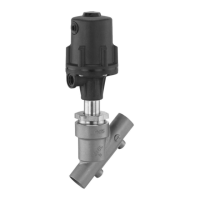
The GEMÜ 1436 cPos makes it possible to use digital inputs
for specic functions.
It is also available to order with two exclusively digital inputs. In
addition to this, it provides the option of using the actual value
and set value inputs as digital inputs under certain conditions.
The wiring information under 6.7.1 only applies when the
GEMÜ 1436 cPos is used without the optional digital input
card.
The digital inputs facilitate the use of dierent functions to
control the positioner in addition to the analogue control
signals. For example, this means up to four parameter sets with
dierent settings can be stored and called up by two digital
inputs through a logical connective (ParmSet Bx function).
The positioner can be stopped by the signal from a digital input
(automatic control system deactivated, current valve position is
maintained) or started up by the valve safety position (function
OFF/ON or Safe/On). Furthermore, the output source of the
analogue actual value output is controlled externally (function
Poti/Ix).
On the Probus DP and DeviceNet eldbus versions, the digital
input functions can be used in addition as standard and do not
need to be ordered separately.
 Loading...