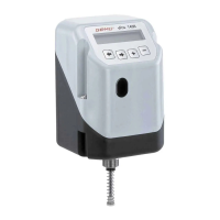
1436 cPos
®
7 / 24
Contents
1 Notes for your safety 7
2 Mechanical mounting 7
2.1 Mounting to linear actuators 7
2.1.1 Preparation of the valve actuator 7
2.1.2 Assembling the travel sensor 7
2.1.3 Mounting the positioner 8
2.2 Mounting to quarter turn actuators 8
2.2.1 Preparation of the valve actuator 8
2.2.2 Assembling the travel sensor 8
2.2.3 Mounting the positioner 9
2.2.4 Checking the mounted assembly 9
2.3 Remote mounting to linear or
quarter turn actuators 9
2.3.1 Preparation of the valve actuator 9
2.3.2 Assembling the travel sensor 9
2.3.3 Checking the mounted assembly 9
2.3.4 Mounting the mounting bracket 9
2.3.5 Connecting the travel sensor 9
3 Pneumatic connections 10
4 Electrical connections 10
4.1 Standard 10
4.2 Profibus DP 11
4.3 DeviceNet 11
4.4 Connection assignment of M12
plug for external travel sensor 11
5 Initialisation and commissioning 12
5.1 Electrical and pneumatic
connection 12
6 Menu structure 14
6.1 Menu structure
1. Service 14
6.2 Menu structure
2. SetBasics 16
6.3 Menu structure
3. SetFunction 18
6.4 Menu structure
4. SetCalibration 20
6.5 Menu structure
5. Communication 22
1 Notes for your safety
Please refer to the safety notes included
in the GEMÜ 1436 cPos
®
operating
instructions on the enclosed CD-ROM.
If you do not have this CD-ROM, please
contact GEMÜ.
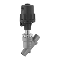
2 Mechanical mounting
2.1 Mounting to linear actuators
2.1.1 Preparation of the valve actuator
G The actuator must be in the zero position
(actuator vented).
G Should there be an optical position
indicator in the actuator (a red spindle), it
must be removed.
2.1.2 Assembling the travel sensor
The travel sensor is assembled using a
mounting kit 1436S01Z... consisting of a
spring, an operating bush and a threaded
adapter (if applicable).
The mounting kit depends on the valve type.
CAUTION
Pretensioned spring!
® Damage to the device.
● Slowly relax spring.
CAUTION
Damage to the spindle surface may
lead to failure of the travel sensor!
1. Pull out the spindle of the travel sensor
up to the limit stop.
Travel sensor
2. Push the spring over the spindle.
3. Fix the spindle at point a - (the spindle
must not be damaged during this
process).
Travel sensor Spindle
a Spring
Operating bush
4. Screw the operating bush onto the
spindle.
a
 Loading...