EasyManua.ls Logo

Genasun GVB-8-WP Series - User Manual

Default Icon
8 pages
To Next Page IconTo Next Page
Loading...
GVB-8-Pb-12V-WP: 12V Lead-Acid/AGM/Gel/Sealed/Flooded
GVB-8-Pb-24V-WP: 24V Lead-Acid/AGM/Gel/Sealed/Flooded
GVB-8-Pb-36V-WP: 36V Lead-Acid/AGM/Gel/Sealed/Flooded
GVB-8-Pb-48V-WP: 48V Lead-Acid/AGM/Gel/Sealed/Flooded
GVB-8-Li-14.2V-WP: 12V (4s) Lithium Iron Phosphate
GVB-8-Li-28.4V-WP: 24V (8s) Lithium Iron Phosphate
GVB-8-Li-41.7V-WP: 36V (10s) Lithium Cobalt/Magnesium/Nickel
GVB-8-Li-54.2V-WP: 48V (13s) Lithium Cobalt/Magnesium/Nickel
GVB-8-Li-56.8V-WP: 48V (16s) Lithium Iron Phosphate
GVB-8-Li-58.4V-WP: 52V (14s) Lithium Cobalt/Magnesium/Nickel
GVB-8-WP (Boost) Manual
For models:
Waterproof Voltage Boosting Solar Charge Controllers with
Maximum Power Point Tracking
IMPORTANT SAFETY INSTRUCTIONS | SAVE THESE INSTRUCTIONS
GENASUN GV-BOOST WP (ALL MODELS) MANUAL, REVISION 5.0 | 2019
8A Input - 105W/210W/325W/350W
GENASUN
c/o BLUE SKY ENERGY
2598 FORTUNE WAY • SUITE K
VISTA, CA 92081 • USA
https://sunforgellc.com/genasun
Question and Answer IconNeed help?

Do you have a question about the Genasun GVB-8-WP Series and is the answer not in the manual?

Genasun GVB-8-WP Series Specifications

General IconGeneral
BrandGenasun
ModelGVB-8-WP Series
CategoryController
LanguageEnglish

Summary

Safety Instructions

Explosion Hazard and Energized Connections

Warnings against connecting or disconnecting when energized and risks of explosion.

Risk of Fire and Battery Safety

Precautions regarding fire risk, explosive gases from batteries, and short circuits.

GFDI and Disconnect Device Requirements

Notes the absence of GFDI and disconnect devices, advising NEC consultation.

Product Certifications

CE Certification

Details compliance with European EMC standards.

FCC Certification

Details compliance with US Radio Frequency Devices regulations.

RoHS Compliance

Details compliance with Restriction of Hazardous Substances directive.

Inspection & Maintenance

Installation & System Connections

Mounting the Controller

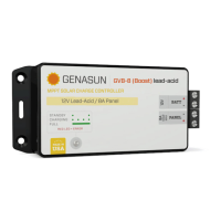
Securely mount the controller near the battery using provided holes or appropriate means.

Connecting the Solar Panel

Connect the solar panel to the +PANEL and –PANEL terminals as per system requirements.

Connecting the Battery

Connect the battery to the +BATT and -BATT terminals, noting potential spark.

Status Indication

LED Run;Charge Indication

Describes the LED status for standby, charging (low/high current), current limit, and battery charged states.

LED Error Indication

Details LED error codes for overheat, overload, battery voltage too high/low, and internal errors.

Troubleshooting

Troubleshooting LED Indicators

Guides on what to check if the LED indicator will not light or displays unlisted indications.

Fuse Replacement and Common Issues

Addresses blown fuses, troubleshooting charging problems, and fuse replacement procedures.

Related product manuals