Edificio Genebre. Av. de Joan Carles I, 46-48
08908 L'Hospitalet de Llobregat. Barcelona (Spain)
genebre@genebre.es - www.genebre.es
7e. Double check the correct assembly of the actuator, confirming that the open position
pistons are of equal distance from the cylinder border.
8. End cap mounting:
8a. Insert the end cap O-Rings (ref. 23) into their grooves by following the shape of the grooves
with a finger to ensure that the O-Rings are properly seated.
8b. Insert the stop bolt, nut and o’ring (ref. 18, 19, & 20) on tha lateral of body (ref. 4).
8c. Insert the indicator (ref. 2 & 3) and the seeger (ref. 1) on the pinion.
8d. Insert the end cap (ref. 25) on the body and tighten the screw (ref. 26) in an alternating order.
9. Adjustment:
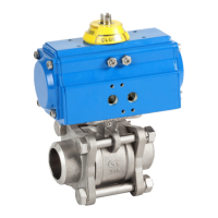
• Supply low pressure compressed air to Port B (see drawings). Using a
hex key wrench, turn the regulation screw (right) until the pinion shaft is
perpendicular to the actuator axis (0° position); tighten the nut.
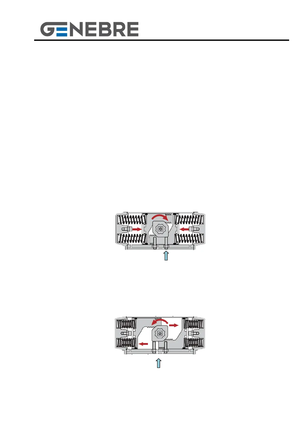
• Next, supply low pressure compressed air to Port A to open the actuator. The pinion
shaft must be at a 90° position (with respect to the 0° position), aligned with the
actuator axis. If it is not aligned, act on the stop bolt (left) and tighten the nut.