Edificio Genebre. Av. de Joan Carles I, 46-48
08908 L'Hospitalet de Llobregat. Barcelona (Spain)
genebre@genebre.es - www.genebre.es
• Note: Do not disassemble the actuator end caps when air pressure is applied to the
actuator.
4. Actuators Installation
GNP actuators can be fitted on many styles of quarter-turn valves, including ball, butterfly
and plug and dampers in accordance with the instructions contained in this chapter.
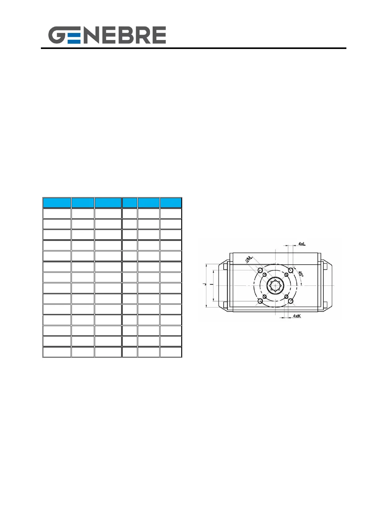
The flange is an integral part of the body and is designed with ISO 5211 and Namur (see
Table a and Figures 3.a / 3.b).
(*) one of the two options must be chosen
Table a Figure 3.a
On the top face of GNP actuators there is a NAMUR standard mounting pattern for
easy installation of accessories for position survey and/or control devices Micro Switch
Boxes, Positioners, ect. (H=80 / 130 and G=30)